Magnetic recording system which eliminates skew angle effect

a magnetic recording and skew angle technology, applied in the field of perpendicular magnetic recording systems, can solve the problems of limiting the ability of the writer to write on higher coercivity media, unwanted side writing, etc., and achieve the effect of reducing or eliminating the skew angle effect and higher areal densities

Inactive Publication Date: 2006-01-17
SEAGATE TECH LLC
View PDF26 Cites 21 Cited by
  • Summary
  • Abstract
  • Description
  • Claims
  • Application Information

AI Technical Summary

Benefits of technology

[0008]The present invention provides a perpendicular magnetic recording system which reduces or eliminates the skew angle effect. As used herein, the term “skew angle effect” means unwanted side writing onto previously recorded magnetic tracks caused by misalignment between the write pole and the recording tracks. The present recording system is particularly suitable for data storage applications where large blocks of information are stored and where small modifications in the stored data are not required. Significantly higher areal densities can be achieved since high track pitch can be utilized in this recording scheme. If the writing on the tracks is done in the order of incremental increase of the track numbers, i.e., the writing sequence is track n, track n+1, track n+2, etc., previously recorded adjacent tracks are not adversely affected. For instance, if track n+1 is recorded, track n is not adversely affected in accordance with the present invention. Consequently, when any particular track is recorded, other tracks are not affected, i.e., no track erasure due to non-zero skew angle will occur.

Problems solved by technology

However, due to the change in skew angle as the recording head travels in an arc across the disk and possible misalignment of the write pole, this can result in unwanted side writing when a rectangular shaped write pole is used.
This would limit the ability of the writer to write on higher coercivity media.

Method used


Image

  • Magnetic recording system which eliminates skew angle effect
  • Magnetic recording system which eliminates skew angle effect
  • Magnetic recording system which eliminates skew angle effect

Examples


Embodiment Construction

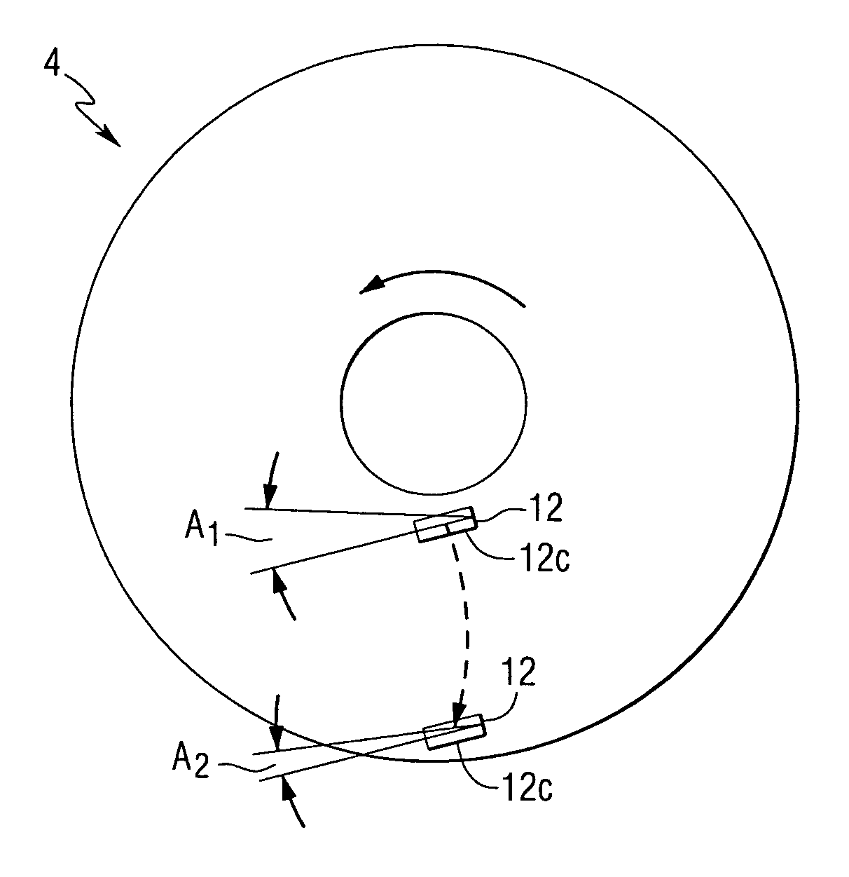
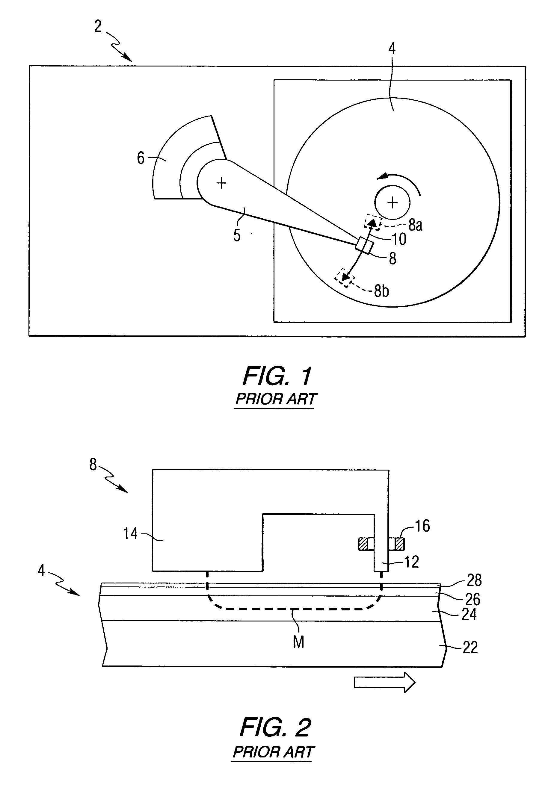
[0021]FIG. 1 schematically illustrates a magnetic hard disk drive 2 including a rotatable magnetic disk 4. An actuator arm 5 is connected to a rotary actuator magnet and coil assembly 6. The magnetic hard disk drive 2 includes a magnetic recording head 8. During recording operations, the recording head 8 travels in an arc 10 between the positions 8a and 8b shown in phantom in FIG. 1. As the recording head 8 moves along the arc 10 over the disk 4, the head 8 is aligned parallel with the circumferential magnetic data tracks of the disk 4 at one location, but is slightly misaligned at a skew angle at other locations along the arc 10. For example, when the recording head 8 is positioned over the disk 4 at its radial innermost position 8a, the maximum skew angle is typically about −12 to −20 degrees. Similarly, when the recording head 8 is located over the disk 4 at the radial outermost position 8b, the maximum skew angle is typically about +12 to +20 degrees. This misalignment results i...


PUM

PropertyMeasurementUnit
compensation angle A2aaaaaaaaaa

Abstract

A perpendicular magnetic recording system is provided which eliminates unwanted side writing to adjacent recording tracks due to the skew angle effect. The system includes a perpendicular magnetic recording head with a write pole that is used to sequentially write to adjacent tracks of a magnetic recording disk. In one embodiment, the write pole is aligned at a compensation angle with respect to the recording tracks which remains greater than zero as the recording head travels in an arc across the disk. When the recording head moves radially inwardly or outwardly across the tracks of the disk, the compensation angle remains greater than zero. Any side writing by the write pole to adjacent tracks is eliminated as the write pole sequentially writes to the next adjacent track. By eliminating the skew angle effect, smaller spacings may be provided between adjacent tracks, thereby increasing data storage densities.

Description

CROSS REFERENCE TO RELATED APPLICATION[0001]This application claims the benefit of U.S. Provisional Patent Application Ser. No. 60 / 221,494 filed Jul. 27, 2000.FIELD OF THE INVENTION[0002]The present invention relates to perpendicular magnetic recording systems, and more particularly relates to a recording system that reduces or eliminates unwanted skew angle effects.BACKGROUND INFORMATION[0003]Perpendicular magnetic recording systems have been developed for use in computer hard disk drives. A typical perpendicular recording head includes a trailing write pole, a leading return or opposing pole magnetically coupled to the write pole, and an electrically conductive magnetizing coil surrounding the yoke of the write pole. The bottom of the opposing pole has a surface area greatly exceeding the surface area of the tip of the write pole.[0004]Conventional perpendicular recording media typically include a hard magnetic recording layer and a soft magnetic underlayer which provide a flux pa...

Claims


Application Information

Patent Timeline
Patent Type & Authority Patents(United States)
IPC IPC(8): G11B20/20G11B5/596G11B5/00G11B5/012G11B5/48G11B5/55G11B5/56
CPCG11B5/012G11B5/4886G11B5/56G11B5/5521G11B2005/0029
Inventor LITVINOV, DMITRIKHIZROEV, SAKHRATGUSTAFSON, ROY WALLACE
Owner SEAGATE TECH LLC
Why Eureka
Try Eureka