This helps you quickly interpret patents by identifying the three key elements:
Problems solved by technology
Method used
Benefits of technology
Benefits of technology
[0017]In order to solve these problems, it is an object of the present invention to increase the degree of freedom for the collaboration between objects or computers connected to a network, and to provide an object collaboration apparatus for constructing a system in which such collaboration processing such as interaction and cooperation between groups of computers or objects is performed, and, in an object-oriented environment, distributed processing of a task is flexibly executed, and which changes progressively.
Problems solved by technology
In order to achieve the first configuration mentioned above, it is not enough simply to provide an application as a component, a framework in which objects dynamically provide and organize functions while interacting with each other is necessary.
However, when collaborating objects are intimately related, depending on each other's internal condition and function, it is difficult to dynamically construct functions by the interaction of these objects.
Method used
Image
Click on the blue label to locate the original text in one second.
Reading with bidirectional positioning of images and text.
Examples
first embodiment
[0133]The first embodiment describes an object collaboration apparatus in which, in an environment where accessible hard disks are distributed on the network, data can be stored regardless of disk capacity by introducing a method for dynamically determining a hard disk to store data.
[0134]FIG. 13 shows a block diagram outlining an object collaboration apparatus, which dynamically determines a hard disk to store data on. In FIG. 13, numeral 1301 denotes a terminal as a requesting object. Numeral 1302 denotes a disk server object. Numeral 1303 denotes a hard disk. Numeral 1304 denotes a shared communication channel. The requesting object 1301 and the disk server object 1302 monitor the same shared communication channel 1304.
[0135]When the terminal 1301 wants to store X megabyte of data, it sends out a requesting message (call for proposal message) [terminal ID, query, X, *], as shown in FIG. 14(a), into the shared communication channel 1304. Each disk server object 1302 has the reacti...
second embodiment
[0137]The second embodiment describes an object collaboration apparatus which efficiently utilizes CPU resources distributed over a network.
[0138]FIG. 16 is a block diagram outlining an object collaboration apparatus in accordance with the second embodiment, which efficiently utilizes CPU resources distributed over a network. In FIG. 16, numeral1601 denotes a terminal that is a requesting object. Numeral 1602 denotes a CPU server object. Numeral 1603 denotes a shared communication channel. The requesting object 1601 and the CPU server object 1602 monitor the same shared communication channel 1603.
[0139]When the terminal 1601 wants to do a large load calculation, it sends out a requesting message (call for proposal message) [terminal ID, query, x,], shown in FIG. 17(a), into the shared communication channel 1603. Each CPU server object 1602 has the reaction table 703 shown in FIG. 17(b), and in response to the requesting message (call for proposal message), the CPU server object retu...
third embodiment
[0142]The third embodiment describes an object collaboration apparatus that utilizes WWW (world wide web, referred to as “WWW” in the following) server resources distributed on a network.
[0143]FIG. 19 shows a block diagram outlining an object collaboration apparatus in accordance with the third embodiment, which utilizes WWW server resources distributed on a network. In FIG. 19, numeral 1901 denotes a WWW client terminal that is a requesting object. Numeral 1902 denotes a WWW server object. Numeral 1903 denotes a network. The requesting object 1901 and the WWW server object 1902 are connected via the network 1903.
[0144]When the terminal 1901 wants to connect the desired URL (universal resource locator) and retrieve data, it sends out a requesting message (call for proposal message) [terminal ID, query, x], as shown in FIG. 20(a), onto the network 1903. Each WWW server object has a reaction table 703 shown in FIG. 20(b), which reacts to the requesting message. Then, the WWW server ob...
PUM
Abstract
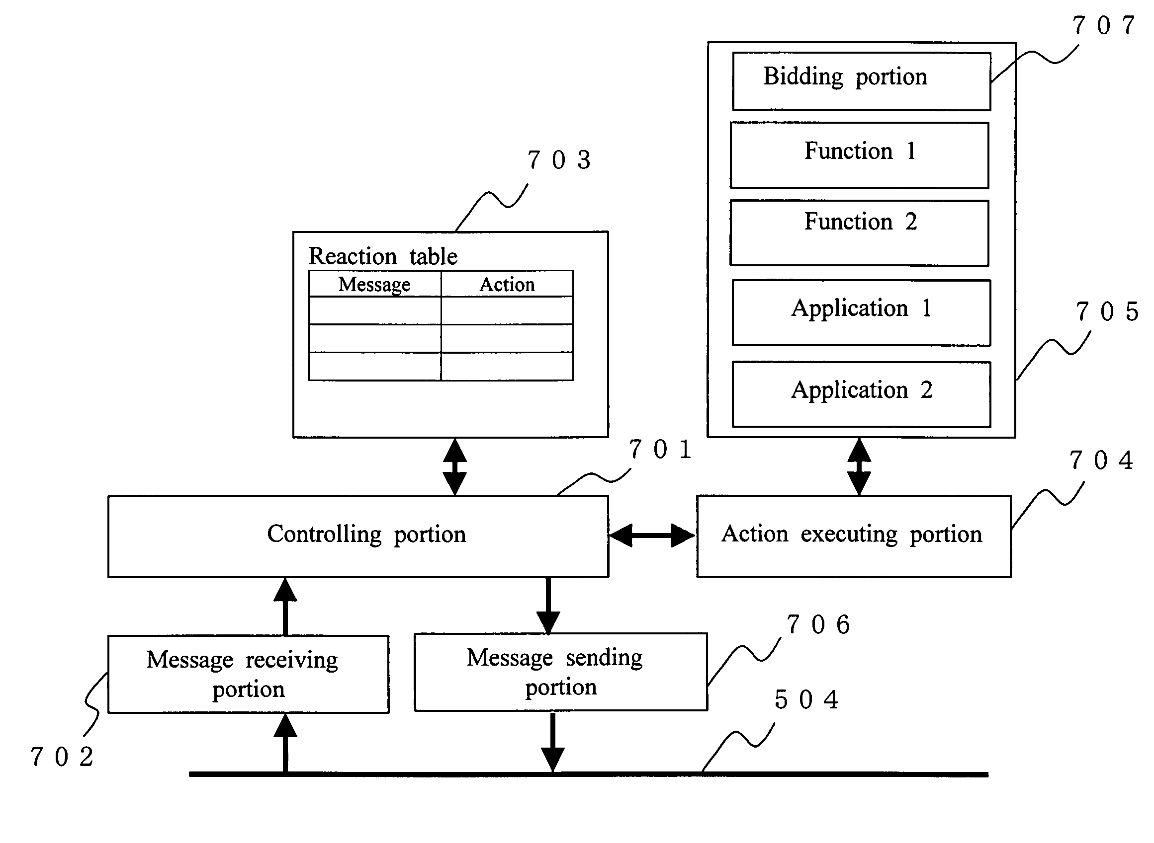
An object collaboration apparatus is driven by a message action relation, and can dynamically build a collaboration between objects using a bidding system. A task initiator object circulates a requesting message, indicating the service content that the task initiator object wants to request, on a shared communication channel 504, and this requesting message is received by each service object. If an action that is a reaction to the message is listed in a reaction table 703 stored by the service objects, the service objects create and return a bidding message, which includes a bidding value, for example the CPU load ratio, with the bidding portion 707. An arbitrating portion of the initiator object receives all bidding messages in a certain period of time, and, in consideration of parameters such as the bidding value and the communication time between objects, determines and awards the bid to the bid-winning object. Then, it sends out the requested processing information together with the bid awarding message. The bid-winning object processes the requested task with an action execution portion 704.
Description
BACKGROUND OF THE INVENTION[0001]1. Field of the Invention[0002]The present invention relates to an object collaboration apparatus for performing collaboration processing such as interaction and cooperation among a group of computers or objects. More particularly, the present invention relates to an object collaboration apparatus for providing a system on a computer network that can adjust to environmental changes and progressive system changes flexibly by generating and organizing a plurality of processes dynamically in an object-oriented environment.[0003]2. Description of the Related Art[0004]As the computer networks shave become widespread in recent years, the systems in which a plurality of objects, which are distributed on a computer network, perform a process while collaborating with each other have been increasing. Research for techniques for object collaboration systems focuses mainly on the object oriented programming technologies and software component technology. One exa...
Claims
Application Information
Patent Timeline
Application Date:The date an application was filed.
Publication Date:The date a patent or application was officially published.
First Publication Date:The earliest publication date of a patent with the same application number.
Issue Date:Publication date of the patent grant document.
PCT Entry Date:The Entry date of PCT National Phase.
Estimated Expiry Date:The statutory expiry date of a patent right according to the Patent Law, and it is the longest term of protection that the patent right can achieve without the termination of the patent right due to other reasons(Term extension factor has been taken into account ).
Invalid Date:Actual expiry date is based on effective date or publication date of legal transaction data of invalid patent.

