Accelerator and crop processor movement

a technology of accelerator and crop processor, which is applied in the direction of mowers, agricultural tools and machines, and mowers, can solve the problems of unnecessary wear of rollers, difficult and cumbersome tasks, and insufficient cutting alone, so as to avoid any risk of blockag

Active Publication Date: 2006-01-24
BLUE LEAF I P INC +1
View PDF9 Cites 22 Cited by
  • Summary
  • Abstract
  • Description
  • Claims
  • Application Information

AI Technical Summary

Benefits of technology

[0011]The present invention differs from EP 1 229 778 in that the latter maintains the housing of the accelerator stationary while moving only its rotor. Thus, the accelerator housing confining the crop material and guiding it towards the discharge spout remains in the same position regardless of the position of the rotor of the accelerator. By contrast, in the present invention, the housing of the accelerator moves with the rotor, which avoids any risk of a blockage developing within the housing of the accelerator.

Problems solved by technology

However, when harvesting maize for silage purposes, the cutting alone does not suffice due to the presence of kernels in the crop.
The kernels need to be cracked in order to release the nutrient, as uncracked kernels are hard for animals to digest.
As cutting alone is insufficient to crack all the kernels, the crop is additionally passed through a crop processor which comprises two closely adjacent rollers, typically having serrated surfaces, which rotate such that there is slippage between the adjacent surfaces.
When chopping kernel-free crops, such as grass or alfalfa, the crop processor is not required and leaving it in place in the crop flow path results in its rollers being unnecessarily subjected to wear.
To avoid such wear, it has previously been proposed to remove the crop processor from the vehicle, but the size and weight of the crop processor make this a difficult and cumbersome task.
In this case, it was found that the crop does not have sufficient momentum when discharged from the cutter to cross the space normally occupied by the crop processor and reach the accelerator, resulting in a tendency to develop a blockage between the cutter and the accelerator.
However, the mechanism described in EP 1 229 778 itself suffers from certain disadvantages in that there is a tendency for crop to create a blockage upstream of the accelerator when the latter is moved into its position nearer the cutter.

Method used


Image

  • Accelerator and crop processor movement
  • Accelerator and crop processor movement
  • Accelerator and crop processor movement

Examples


Embodiment Construction

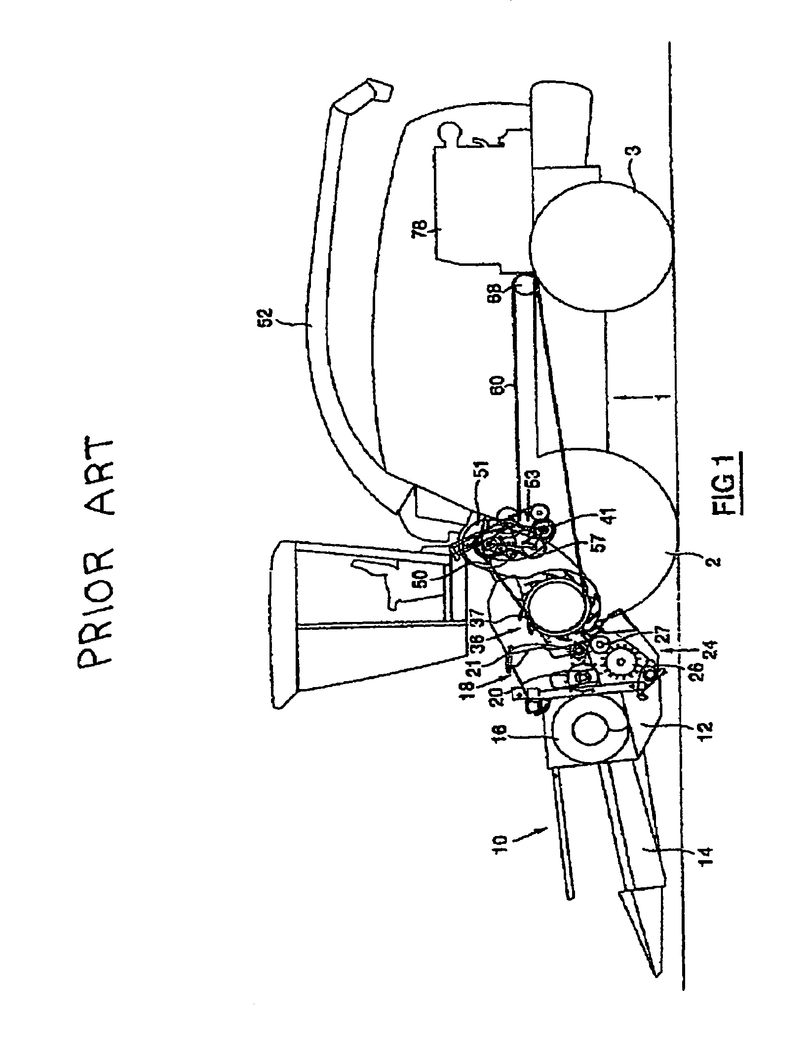
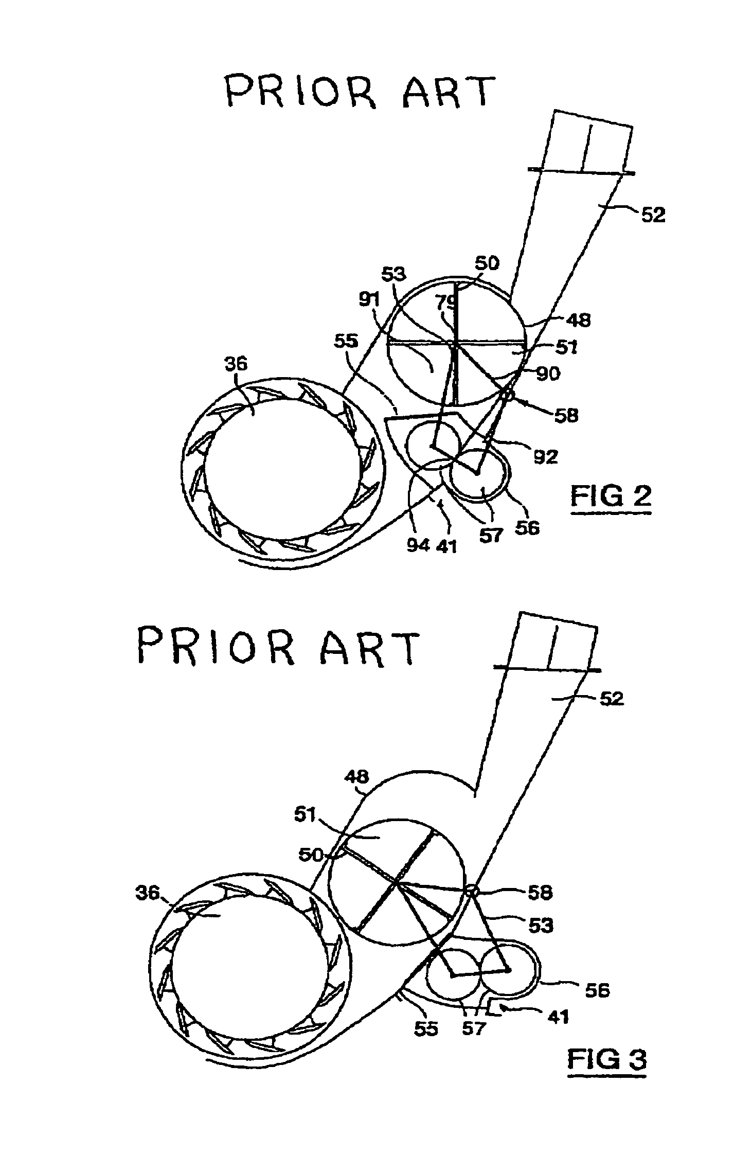
[0025]FIGS. 1 to 5 represent a prior art forage harvester as described in EP 1 229 778 which will be described herein for a better understanding of the problem solved by the present invention. In the description below, The terms “front”, “rear”, “forward”, “rearward”, “right” and “left” are determined with respect to the normal direction of movement of the harvester in operation and are not to be construed as limiting terms.

[0026]FIGS. 1 to 5 show a forage harvester having a main frame 1 on which are mounted ground engaging traction wheels 2 and steering wheels 3. The forage harvester is shown equipped with a crop collecting apparatus, in the form of a row crop attachment 10, suitable for the harvesting of maize. This attachment can be replaced with a conventional windrow pick-up device or a conventional cutter bar attachment, depending on the type of crop to be harvested. Customarily, the row crop attachment 10 comprises an attachment frame 12, which supports a plurality of row cro...


PUM


Abstract

In a forage harvester having a cutter for chopping gathered crop material, a unit is arranged downstream of the cutter, the unit including an accelerator arranged in the path of crop flow for propelling the crop towards a discharge spout, and a crop processor for cracking kernels which is selectively movable into and out of the crop flow path at a location between the cutter and the accelerator. The accelerator comprises a rotor and housing which are together movable towards the cutter when the crop processor is withdrawn from the crop flow path.

Description

CROSS REFERENCE TO RELATED PATENT APPLICATIONS[0001]This Patent Application claims priority under 35 U.S.C. § 119 to GB0411826.1, filed on May 27, 2004 titled, “Accelerator and Crop Processor Movement”, the full disclosure of which is hereby fully incorporated herein by reference.FIELD OF THE INVENTION[0002]This invention relates to forage harvesters.BACKROUND OF THE INVENTION[0003]Forage harvesters are machines which chop crop gathered from a field into small pieces to produce animal feed. In the case of crops such as grass or alfalfa, these will have been pre-cut and left to dry in the sun, so that the crop need only be gathered by the harvester. With other crops, such as maize, the forage harvester may also be required to cut the crop. Thus, the harvesters may be fitted with different headers to suit the crop being harvested.[0004]The crop, whether cut maize or gathered grass, is fed into a rotating knife drum or cutter which comminutes the product. With grass crops, this alone i...

Claims


Application Information

Patent Timeline
Patent Type & Authority Patents(United States)
IPC IPC(8): A01D61/00A01D43/08A01D43/10
CPCA01D43/10A01D43/081
Inventor VAN VOOREN, SANDOR W.
Owner BLUE LEAF I P INC
Why Eureka
Try Eureka