

Resin intake manifold
- Summary
- Abstract
- Description
- Claims
- Application Information
AI Technical Summary
Benefits of technology
Problems solved by technology
Method used
Image

Examples
first embodiment
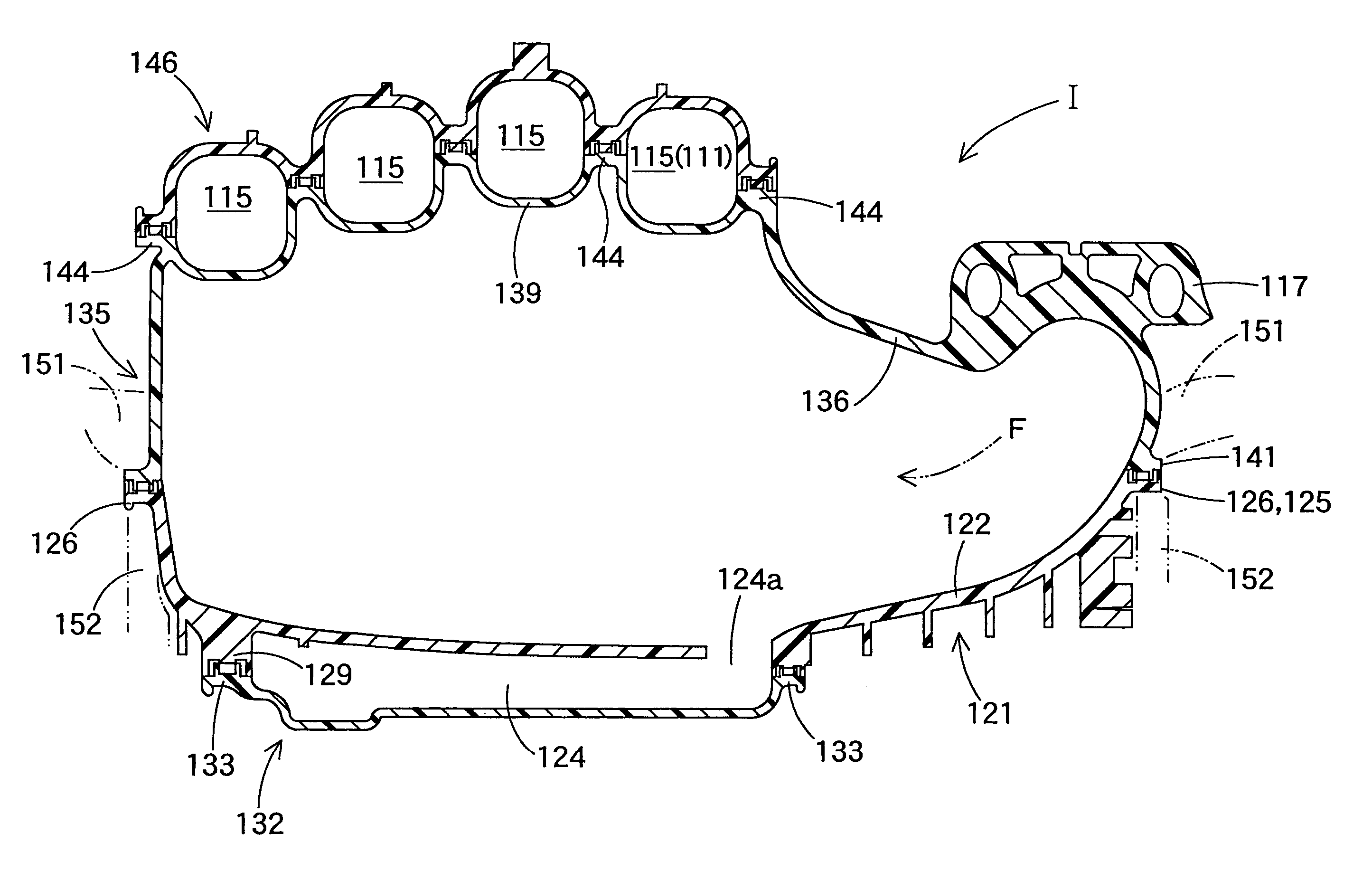
[0078]FIGS. 2 to 11 show a resin intake manifold in accordance with a A resin intake manifold I is constituted by four separated bodies which are respectively formed by a thermoplastic synthetic resin such as 6 nylon with filler or the like and comprise a cover member 21, a base member 31 positioned below the cover member 21, a tank and resonator combined member 43 positioned below the base member 31, and a resonator bottom member 45, as shown in FIGS. 2 to 5. Further, the intake manifold I in accordance with the embodiment is assembled between a throttle body (not shown) and a cylinder head side of an engine, and is structured such that a flow passage 11 of an intake fluid F (refer to FIG. 5), and a resonator 19 communicated with a part of the intake flow passage 11 are provided.
[0079]The intake flow passage 11 is structured such as to be provided with a surge tank 14 positioned in an upstream side, and distribution passages 15 for distributing an intake fluid F from the surge tan...
second embodiment
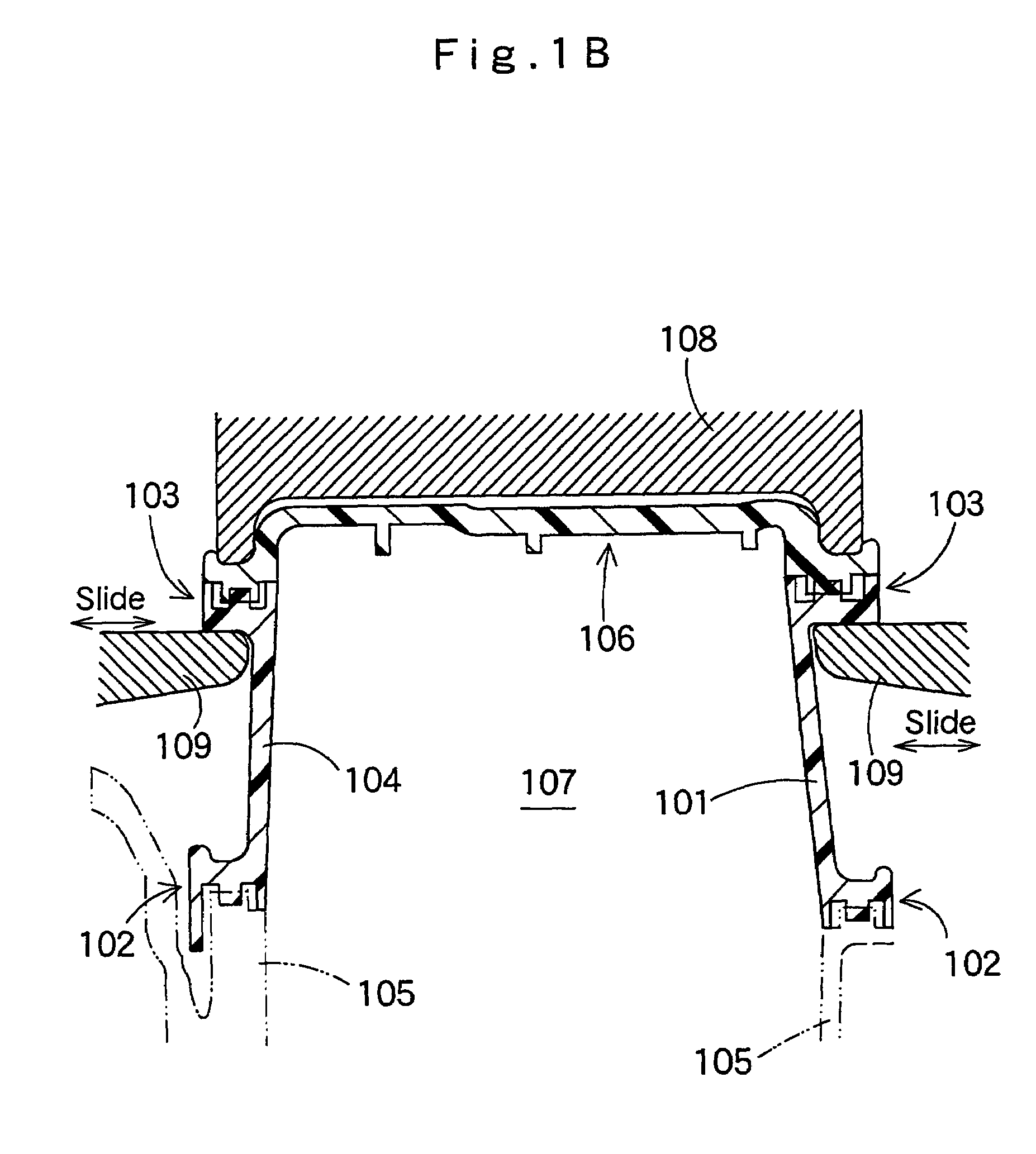
[0115]Further, in the resin intake manifold I in accordance with the second embodiment, even in the case that the outer weld collar portion 126 for welding to the second piece 135 is provided in one end portion 123a of the peripheral wall portion 123 in the first piece 121, the weld portion 129 to the third piece 132 in another end portion 123b of the peripheral wall portion 123 is formed as the inner weld collar portion 130 which can prevent an interference with the pressurizing jig 52 supporting the outer weld collar portion 126 at a time of welding the first piece 121 to the second piece 135.
[0116]Accordingly, at a time of welding the first piece 121 to the third piece 132, as shown in FIG. 22, the inner weld collar portion 130 of the peripheral wall portion 123 can be supported by the pressurizing jig 148 arranged in the inner peripheral side of the peripheral wall portion 123. Since the pressurizing jig 148 can be formed as a simple structure which is not necessary to be slid, ...
third embodiment
[0125]FIGS. 23 to 34 show a third embodiment in accordance with the present invention. FIG. 23 shows a front elevational view of a resin intake manifold 201 used in an in-line four-cylinder engine, FIG. 24 shows a back elevational view of the same, FIG. 25 shows a right side elevational view of same, and FIG. 26 shows a left side elevational view of the same.
[0126]The resin intake manifold 201 is constituted by a first piece 202 positioned in a center portion, a second piece 203 forming a cover portion of an independent intake passage in an upper portion, a third piece 204 positioned in a back surface portion of the first piece and forming a back surface side of a surge tank 224, and a fourth piece 205 positioned in a back surface portion of the third piece 204 and forming a cover portion of a resonator 225. Members of the first piece 202, the second piece 203, the third piece 204 and the fourth piece 205 are formed in a predetermined shape in accordance with an injection molding of...
PUM
| Property | Measurement | Unit |
|---|---|---|
| Shape | aaaaa | aaaaa |
Abstract
Description
Claims
Application Information