Heat exchanger and method of manufacturing core plate

a technology of heat exchanger and core plate, which is applied in the direction of heat exchanger types, indirect heat exchangers, light and heating apparatus, etc., can solve the problem of inability to ensure a sufficiently high mechanical strength, and achieve the effect of preventing deterioration of the manufacturing yield of the core plate and reducing the stress

Active Publication Date: 2006-01-24
DENSO CORP
View PDF9 Cites 34 Cited by
  • Summary
  • Abstract
  • Description
  • Claims
  • Application Information

AI Technical Summary

Benefits of technology

[0010]Accordingly, it is possible to prevent a difference of the mechanical strength between the core plate (5) and the tubes (2) from increasing. Therefore, stress concentration upon the joint portion between the core plate (5) and the tubes (2) can be prevented. As a result, it becomes possible to enhance the mechanical strength of the heat exchanger and the reliability (durability) of the joint portion between the core plate (5) and the tubes (2).
[0012]Due to the above structure, an oblique face connected to the top portion of the bent portion (5a) can be made to function as a guide face used in the case of inserting the tube (2) into the hole (5c). Therefore, the working property can be enhanced when the tubes (2) are inserted and incorporated into the core plate (5).
[0014]Due to the above structure, the working property can be further enhanced when the tubes (2) are inserted and incorporated into the core plate (5).
[0017]Accordingly, it is possible to prevent the core plate (5) from being deformed when the wave-shaped portion (5b) is formed, and deterioration of the manufacturing yield of the core plate (5) can be prevented.
[0023]Accordingly, it is possible to prevent the core plate (5) from being deformed when the wave-shaped portion (5b) is formed, and deterioration of the manufacturing yield of the core plate (5) can be prevented.

Problems solved by technology

Accordingly, it is impossible to ensure a sufficiently high mechanical strength.

Method used


Image

  • Heat exchanger and method of manufacturing core plate
  • Heat exchanger and method of manufacturing core plate
  • Heat exchanger and method of manufacturing core plate

Examples


first embodiment

[0038](First Embodiment)

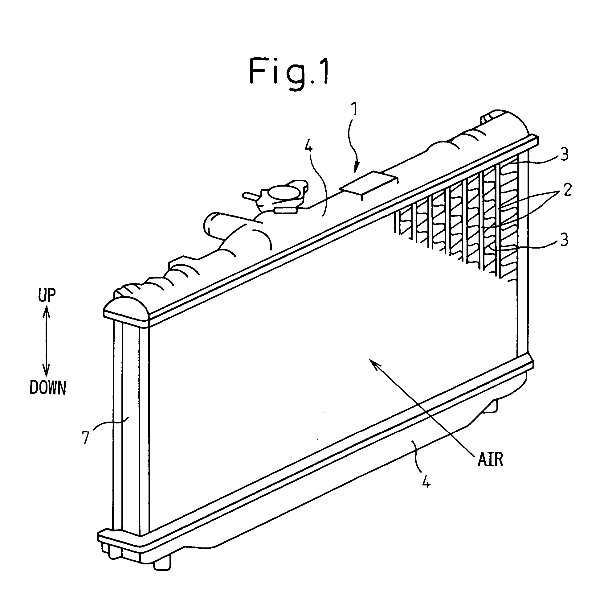
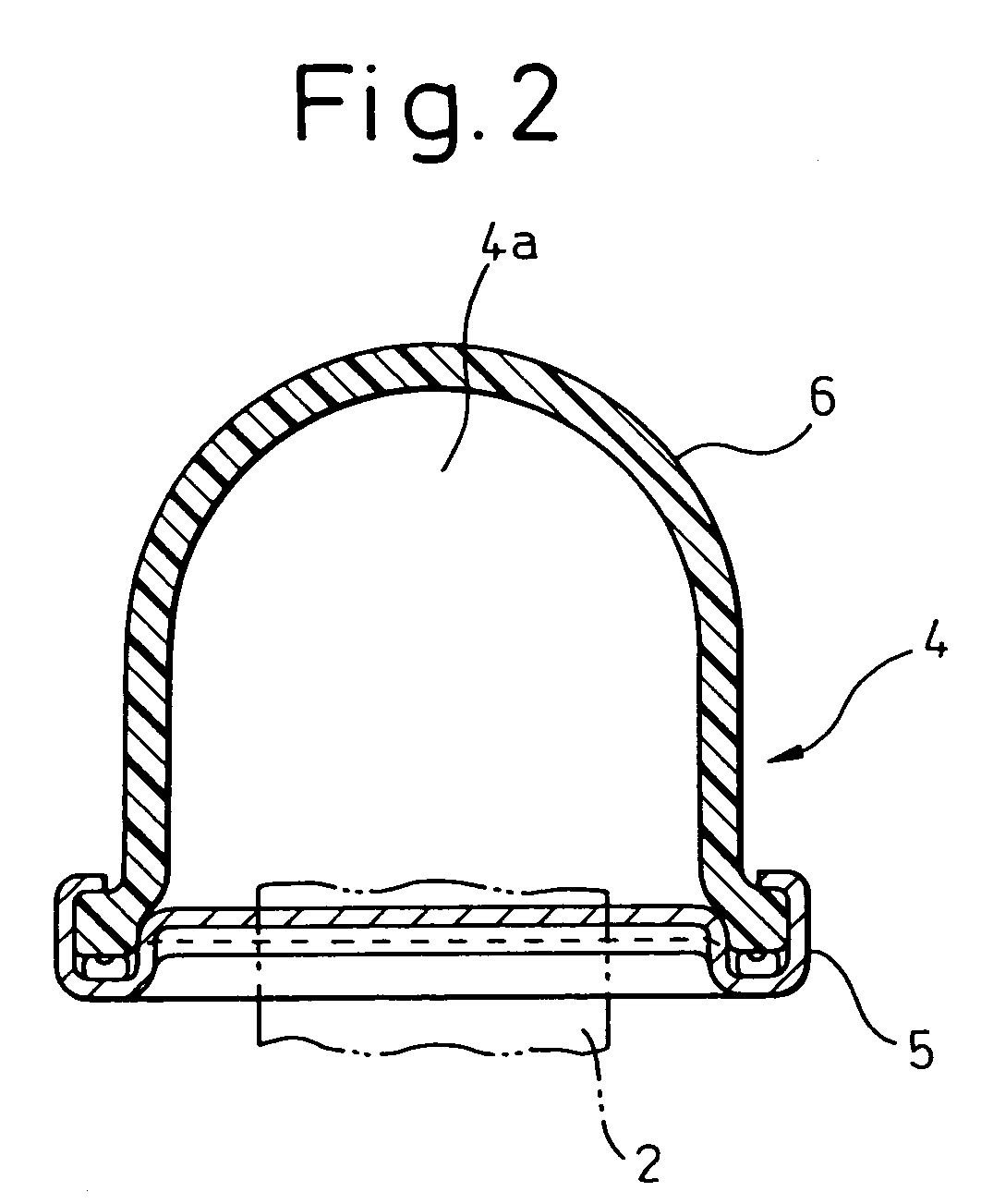
[0039]In this embodiment, a heat exchanger of the present invention is applied to a radiator for cooling an engine (internal combustion engine) which is a power source to move a vehicle. FIG. 1 is a perspective view of the radiator 1 of the embodiment, FIG. 2 is a sectional view of the header tank, FIG. 3A is a plan view of the core plate, FIG. 3B is a side view of the core plate, FIG. 4 is a perspective view of the core plate, FIG. 5 is a perspective sectional view of the core plate, and FIGS. 6A and 6b are sectional views of the core plate.

[0040]In FIG. 1, the tube 2 is a flat pipe in which cooling water flows. In this embodiment, the longitudinal direction of the tube 2 coincides with the vertical direction, and the sectional profile of the tube 2 is formed so that the major axis direction can coincide with the air flowing direction. In this connection, the direction of the minor axis of the tube 2 is substantially perpendicular to the air flowing directio...

second embodiment

[0057](Second Embodiment)

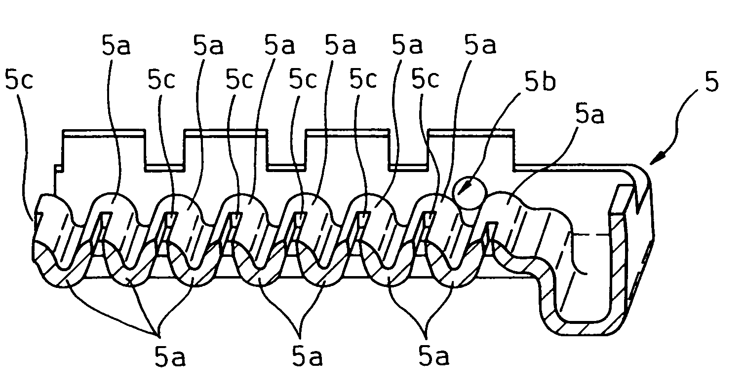
[0058]In the core plate 5 relating to the first embodiment, in the circumference of the hole 5c which is formed into a flat shape, only the circumference on the minor axis direction side of the hole 5c is inclined with respect to the inserting direction of the tube 2. However, in this embodiment, as shown in FIG. 8, the entire circumference of the hole 5c is inclined with respect to the inserting direction of the tube 2.

[0059]Due to the foregoing, the oblique face in the entire circumference of the hole 5c, that is, the oblique face 5d on the minor axis direction side of the hole 5c and the oblique face 5e on the major axis direction side of the hole 5c function as a guide face in the case of inserting the tube 2 into the hole 5c.

[0060]Accordingly, the working property can be enhanced in the case where the tubes 2 are inserted and incorporated into the core plate 5.

third embodiment

[0061](Third Embodiment)

[0062]This embodiment relates to size in the case of obtaining the work limit in the case of forming the core plate 5 into a wave-shape and also obtaining the necessary mechanical strength.

[0063]Specifically, a ratio (Lp / H) of the wave length size (Lp) of the wave-shaped portion 5b to the difference of elevation (H) of the wave-shaped portion 5b is not less than 0.459 and not more than 0.513.

[0064]In this connection, in this embodiment, the core plate 5 is made of aluminum alloy (JIS (Japanese Industry Standard) A3017), and the thickness t is approximately 1.5 mm.

[0065]In this connection, in this embodiment, Lp is 8.2 mm, H1 is 3.9 mm, and H2 is 6.1 mm in FIG. 9.


PUM

PropertyMeasurementUnit
thicknessaaaaaaaaaa
temperatureaaaaaaaaaa
thicknessaaaaaaaaaa

Abstract

A wave-shaped portion 5b, the profile of which is formed into a wave-shape, is provided on the core plate 5, and tubes are brazed to the core plate 5 under the condition that the tubes are inserted into holes 5c formed in bent portions 5a. Due to the above structure, even when a pitch between the tubes is reduced, it is possible to ensure a sufficiently high mechanical strength of the core plate 5. Accordingly, the occurrence of a big difference in the mechanical strength between the core plate 5 and the tubes can be suppressed. Therefore, stress concentration at a joint portion of the core plate 5 and the tubes can be prevented. As a result, the mechanical strength of a radiator and the reliability (durability) of the joint portion of the core plate 5 and the tubes can be enhanced.

Description

BACKGROUND OF THE INVENTION[0001]1. Field of the Invention[0002]The present invention relates to a heat exchanger. The heat exchanger of the present invention is effectively used when it is applied to a radiator of a water-cooled internal combustion engine in which heat is exchanged between cooling water and air.[0003]2. Description of the Related Art[0004]A conventional radiator includes: a plurality of tubes in which cooling water flows and header tanks, which are arranged on both end sides of the tubes in the longitudinal direction of the tubes and extend in a direction substantially perpendicular to the longitudinal direction of the tubes, communicated with the plurality of tubes. Each header tank includes a core plate into which the tubes are inserted and fixed and a tank portion which, together with the core plate, composes a space in the header tank.[0005]Conventionally, embossed portions, which are respectively formed into a recessed shape or a protruded shape, are provided ...

Claims


Application Information

Patent Timeline
Patent Type & Authority Patents(United States)
IPC IPC(8): F28F9/02B21D13/02B21D53/02B21D53/08F28D1/053F28F9/18
CPCF28F9/182B21D53/085F28F9/0226F28D1/05366Y10T29/4935F28D2021/0094
Inventor OZAKI, TATSUOTOYODA, MASANOBU
Owner DENSO CORP
Why Eureka
Try Eureka