Light panel with enlarged viewing window

a technology of a viewing window and a light panel, which is applied in the field of light panels, can solve the problems of inability to use the viewing window, the length over which the light beams should be enabled to mix, and the length over which the color mixing cannot be enabled, so as to achieve the effect of reducing the required distance or colors for color mixing, reducing the need for color mixing, and reducing the pitch of the light sour

Inactive Publication Date: 2006-01-24
KONINKLIJKE PHILIPS ELECTRONICS NV
View PDF3 Cites 33 Cited by
  • Summary
  • Abstract
  • Description
  • Claims
  • Application Information

AI Technical Summary

Benefits of technology

[0005]The present invention has for an object to obviate or at least decrease the above stated problems and disadvantages of the prior art light panels, to which end according to the invention light panels are provided, which are distinguished in that the array comprises complementary sub-arrays of light sources along at least two of the sides. Since the sub-arrays are complementary, in that by all light sources of the different types the same amount of light is emitted into the light guide as in prior art single array configurations (the same number of light sources) , but from two or more sides while maintaining the general light source pitch, the average distance or pitch between light sources of one of the types, can be decreased. Therewith also the required distance or colors for color mixing is lessened and the viewing window is enlarged. With a proper choice of patterns in the sub-arrays of light sources, this average distance can even be reduced to the pitch between light sources. The latter case can for instance be achieved, when the prior art array along a single side in a pattern RGBG is, according to the present invention, replaced by two sub-arrays along two sides; RBRB along the one or two of the sides and GGGG along the one or two of the other of the sides. Along the side or sides with the pattern GGGG the pitch between light sources of one color is reduced in effect to the pitch between light sources in general. Thereby, along that particular side, the viewing window limiting distance corresponding with an adequate distance for the different colors to mix is reduced to the absolute minimum and only determined by said pitch. According to the present invention the viewing window limiting distance is decreased, whereby, to obtain a viewing window of a specific size, the total configuration can be decreased in size.

Problems solved by technology

However, in the light panels with light sources of at least two types / colors, generating divergent light beams into the panel, a considerable length is required for the colors from the distinct types of light sources to mix and provide the desired color, for instance white.
This distance is a limitation on the viewing window, because in the known light panels, wherein the light sources are arranged along a single side thereof, the pitch between light sources of the same color is a number of times larger than the light source-to-light source pitch.
It will be immediately apparent to one, skilled in the art, that when the light sources are directed into the panel and generate divergent light beams, the length over which the light beams should be enabled to mix, and which therefore can not be used for the viewing window, is considerable.

Method used


Image

  • Light panel with enlarged viewing window
  • Light panel with enlarged viewing window
  • Light panel with enlarged viewing window

Examples


Embodiment Construction

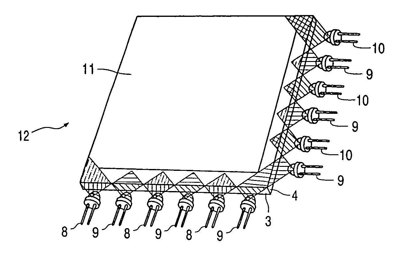
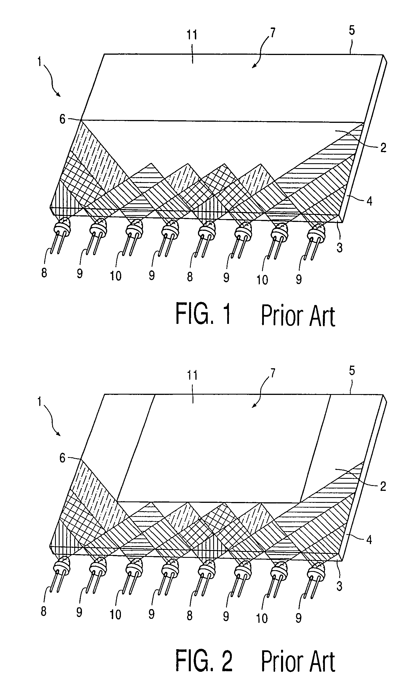
[0012]FIGS. 1 and 2 show essentially the same prior art light panel 1. The light panel 1 comprises a light guide 2 having sides 3, 4, 5 and 6. Further the light guide has a front surface 7 and a back surface (not shown).

[0013]Along side 3 a patterned array of light sources of three types, i.e. colors, is arranged. There are red LED's 8, green LED's 9 and blue LED's 10. Therefore the pattern is RGBG. This is the same both in FIG. 1 and FIG. 2. The difference between FIGS. 1 and 2 is the location, shape and size of the viewing window 11, which in FIG. 1 is defined by the shortest distance at sides 4 and 6, where the viewing window 11 can be arranged, i.e. where the light beams from the LED's 8, 9 and 10 have mixed sufficiently, whereas in FIG. 2 the viewing window 11 is defined by the viewing window limiting distance at the middle of side 3 in the direction of side 5.

[0014]It is apparent from FIGS. 1 and 2, that the viewing window 11 of the prior art light panel are severely restricte...


PUM

PropertyMeasurementUnit
angleaaaaaaaaaa
angleaaaaaaaaaa
coloraaaaaaaaaa

Abstract

The invention relates to a light panel (12), comprising: a light guide having a front surface defining a viewing window (11), a back surface and sides (3, 4) between the front and back surfaces; and a patterned array of light sources (8, 9, 10) of at least two types, which types are distinguished by the color of light emitted by the light sources of said at least two types, said array being arranged along at least one of the sides. Each light source generates in use a divergent light beam of a color into the panel to, in combination, color the panel. Further, the array comprises complementary sub-arrays (8, 9, 8, 9&9, 10, 9, 10) of light sources along at least two of the sides. Since the sub-arrays are complementary, in that by all light sources of the different types the same amount of light is emitted into the light guide as in prior art single array configurations (the same number of light sources), but from two or more sides while maintaining the general light source pitch, the average distance or pitch between light sources of one of the types, can be decreased. Therewith also the required distance or colors for color mixing is lessened and the viewing window is enlarged.

Description

BACKGROUND OF THE INVENTION[0001]The present invention relates to a light panel, comprising: a light guide having a front surface defining a viewing window, a back surface and sides between the front and back surfaces; and a patterned array of light sources of at least two types, which types are distinguished by the color of light emitted by the light sources of said at least two types, said array being arranged along at least one of the sides, wherein each light source generates in use a divergent light beam of a color into the panel to, in combination, color the panel.[0002]Such a light panel is known, for instance from LCD backlighting.[0003]Light panels having light sources of at least two types, i.e. two colors, have several advantages over light panels with single color light sources, for instance phosphor converted white LED's. The so-called white point is adjustable and not for instance determined by the phosphor mix. The available color spaces which is determined by the com...

Claims


Application Information

Patent Timeline
Patent Type & Authority Patents(United States)
IPC IPC(8): F21V8/00F21Y101/02G02F1/13357G09G3/00
CPCG02B6/0068G02B6/0038G02F1/1335
Inventor HOELEN, CHRISTOPH GERARD AUGUSTHARBERS, GERARD
Owner KONINKLIJKE PHILIPS ELECTRONICS NV
Why Eureka
Try Eureka