Surgical clamp pad with interdigitating teeth

a clamping device and interdigitation technology, applied in the field of surgical clamping devices, can solve the problems of devices likewise prone to slipping off trauma of the clamping vessel at the clamping site, and easy slippage, so as to improve the gripping of the vessel or tissue

Inactive Publication Date: 2006-01-24
VITALTEC INT
View PDF19 Cites 85 Cited by
  • Summary
  • Abstract
  • Description
  • Claims
  • Application Information

AI Technical Summary

Benefits of technology

[0009]The present invention provides for opposing surgical clamp members having opposing resilient pads with clamping surfaces that have interdigitating protrusions or “teeth” that extend from the surfaces of the pads for engagement with a vessel. As used herein, the general term “vessel” shall refer to a blood vessel or other tubular body structure. The protrusions are arranged in rows lengthwise along pairs of opposable pads such that when the pads are brought together, the protrusions of one pad interdigitate with the protrusions of the other pad. When engaged with a vessel, portions of the vessel, including the adventitial layer, will be forced into the interdigital spaces between the protrusions, providing for improved gripping of the vessel or tissue. At the same time, the resiliency of the protrusions ensures against trauma to the clamped vessel or tissue.
[0010]The protrusions themselves can be of varying shapes, including cylindrical-shaped protrusions or wedge-shaped protrusions. Where cylindrical protrusions are used, the protrusions can culminate in varying tip shapes, for example, blunt cut, hemispherical or conical tips can be used. The protrusions can also include discrete gripping edges to further increase the traction on an engaged vessel. In every case, the resiliency of the protrusions is such that the protrusions will deflect upon engagement with a vessel but will not distort too greatly from their overall original shape. It is important that the resiliency of the pad as a whole is adequate to impart a cushioning effect upon the clamped vessel, while at the same time the protrusions of the pad retain enough of their original shape to effectively interdigitate with the protrusions of the opposing pad when the pads are brought together in engagement with the vessel. In this manner, the engaged vessel is effectively gripped while minimizing trauma or damage to the vessel. Optimally, the pad itself is of a single-piece construction with the protrusions integrally formed with the remainder of the pad.
[0011]In an embodiment of the invention, the relative resiliency of the pad can be altered by including a series of through holes located below the pad surface and transverse to the length of the pad. The holes can be of varying diameter and varying spacing. One skilled in the art will realize that multiple arrangements of through holes can be used, provided that the result is that the underlying portion of the pad containing the through holes is more easily deflected than the protrusions of the overlying surface portion of the pad. The pad thus provides a greater overall cushioning effect for a clamped vessel while at the same time providing the gripping protrusions with a sufficient hardness to resist excessive deformation upon engagement with a clamped vessel. The through holes can extend along the entire length of the pad or, alternatively, extend only along the portions of pad length, for example, along the center portion of the pad. In this latter configuration, the pad will be more easily deflected along the center portion and stiffer towards the ends of the pad. Vessels clamped in the center of the pads will be restrained from slipping toward the ends of the pads because movement of the vessel in those directions will be resisted in part due to the stiffer resilience of the end portions of the pads.

Problems solved by technology

Such instruments, however, are known to cause trauma to the clamped vessel at the clamping site.
However, this device suffers from the disadvantage that it slips easily.
These devices likewise are prone to slipping off of the clamped vessel.
This can be especially problematic in situations where, due to obstructions, a vessel has been clamped with only the distal tips of the clamp jaws.
In such situations, the vessel can be especially prone to slipping in the direction of the distal tips.
While the Haller device is less traumatic to a vessel than other occlusion devices, it nevertheless has the disadvantage of traumatizing the outer layer of the vessel.
While this device offers a less traumatic way to occlude a vessel, the cohesive-adhesive nature of the bond can result in the removal of some of the adventitial layer of the vessel when disengaging the device.
The hard teeth of this device serve to resist movement of a clamped vessel laterally of the jaw, but do so at increased risk of trauma to the vessel.

Method used


Image

  • Surgical clamp pad with interdigitating teeth
  • Surgical clamp pad with interdigitating teeth
  • Surgical clamp pad with interdigitating teeth

Examples


first embodiment

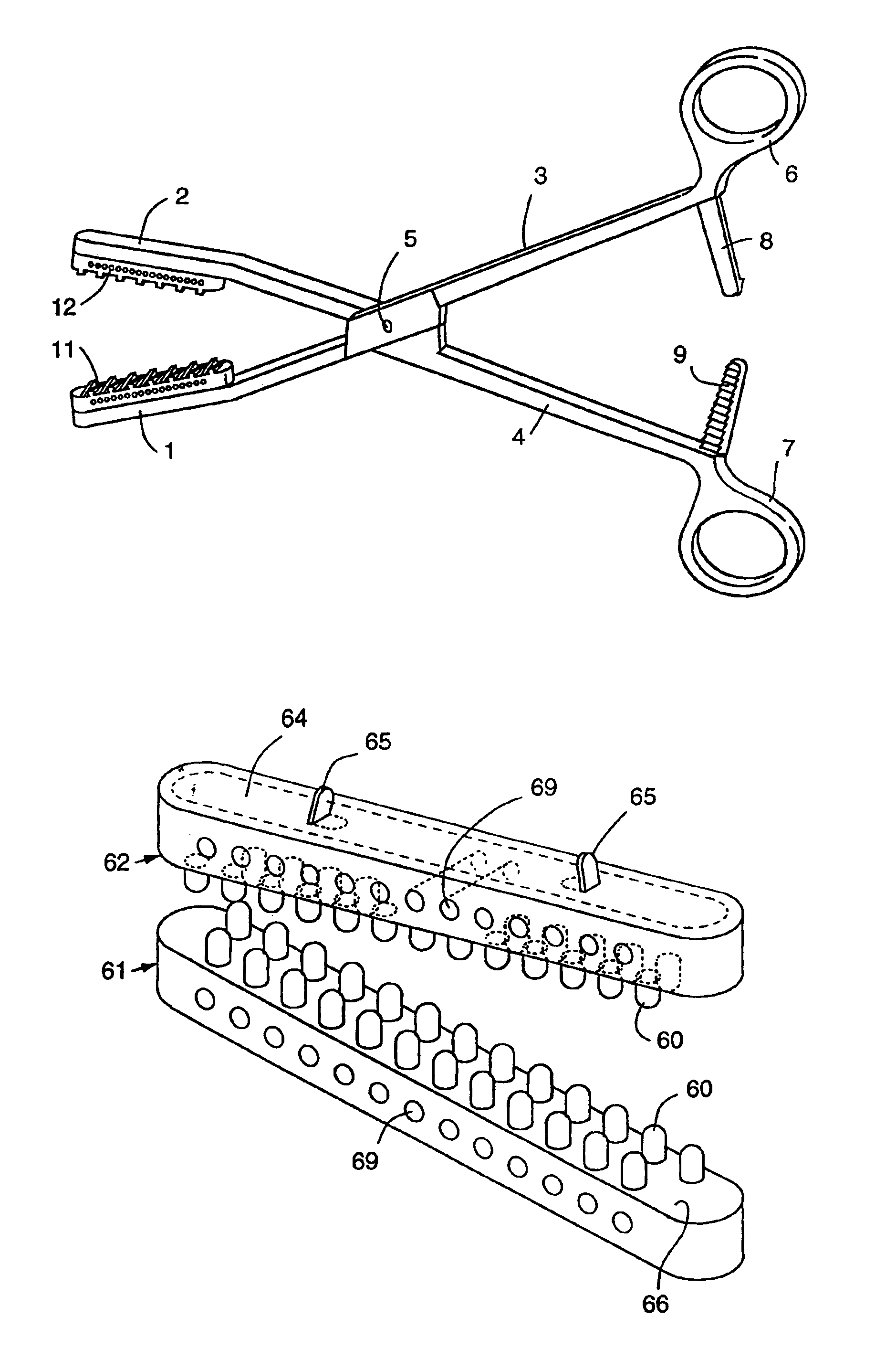
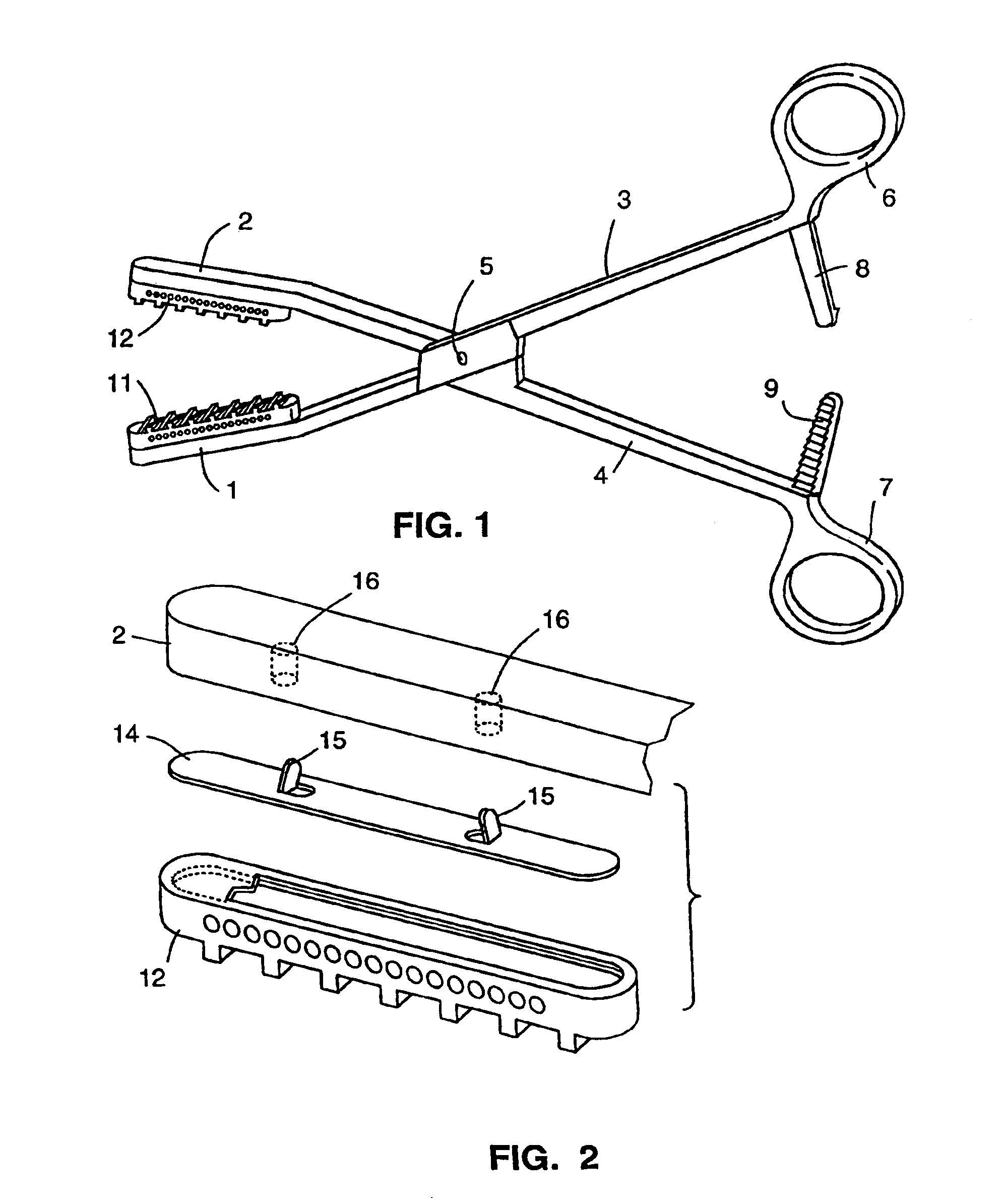
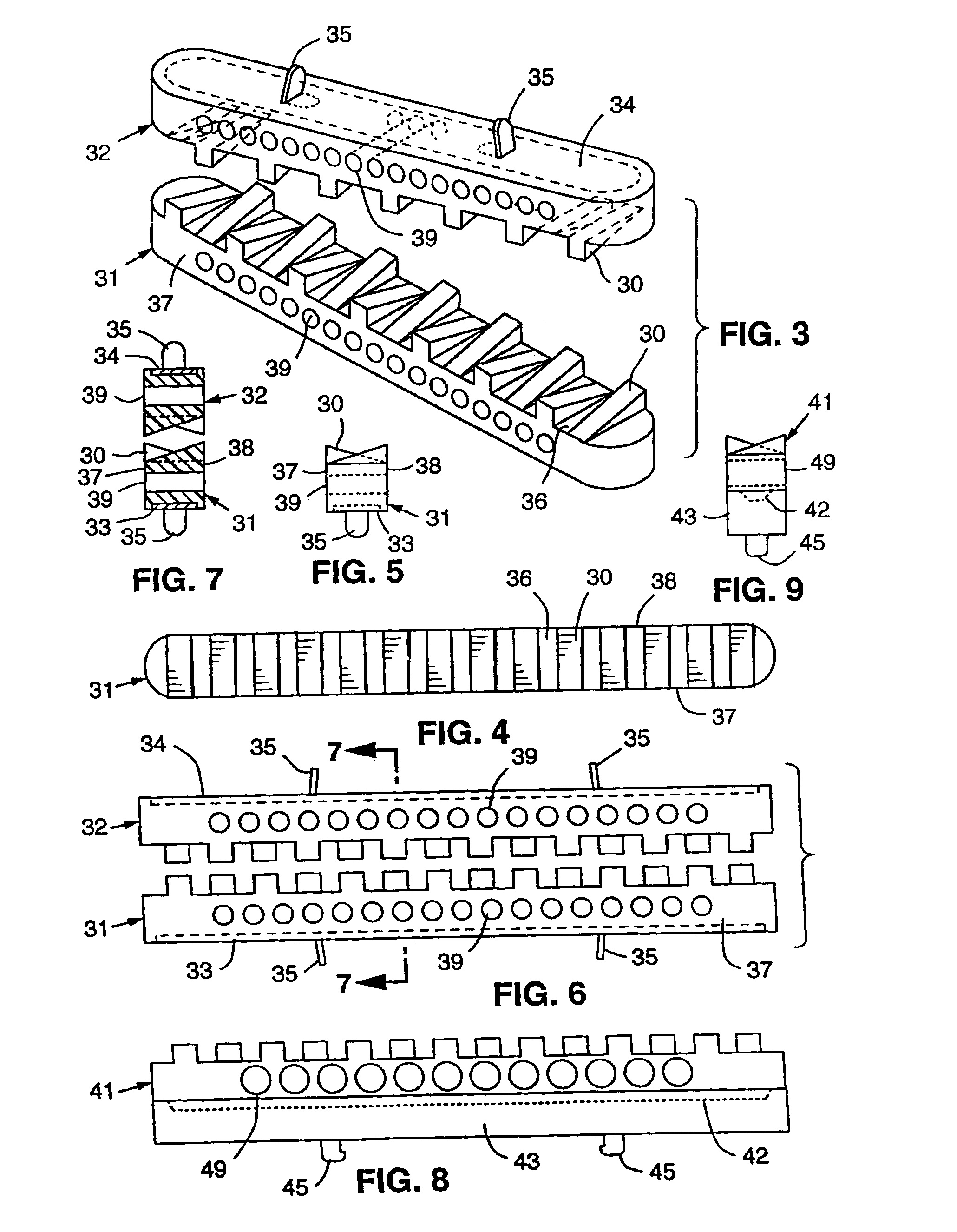
[0043]A first embodiment of a clamping member according to the present invention is depicted in FIGS. 3-9. Resilient pads 31 and 32 are attached to base members 33 and 34, respectively. Pads 31 and 32 are comprised of silicone and formed around base members 33 and 34 by a conventional liquid injection-molding process well known in the art. Once the pads cure or harden, the base members are permanently secured to the pads. Base members 33 and 34 are formed of stainless steel and include spaced apart tabs 35, 35 that can be detachably secured within corresponding recesses in the jaw of a surgical clamp. The tabs are slightly angled toward each other and the respective recesses are undercut so that once the tabs are placed within the recesses, the ends of the tabs snap beneath the undercut, releasably securing the pad to the jaw.

[0044]Protrusions in the general shape of wedges 30 extend from planar surface 36 of each pad 31, 32. The wedges are arranged in rows along the length of each ...

second embodiment

[0051]A second embodiment of a clamping member according to the present invention is depicted in FIGS. 10-14. Resilient pads 61 and 62 are attached to base members 63 and 64, respectively. Preferably, the pads 61 and 62 are of 50 durometer silicone (GE 6050) and are formed around base members 63 and 64 in similar fashion as described above for the first embodiment. Again, base members 63 and 64 are formed of stainless steel, and include tabs 65, 65 that can be detachably coupled to corresponding recesses in the jaw of a surgical clamp. Cylindrical protrusions 60 extend from planar surface 66 of each pad 61, 62. The protrusions 60 are arranged in two rows along the length of each pad 61, 62 with the protrusions of the first row staggered relative to the protrusions of the second row, as depicted in FIG. 11. As shown in FIG. 12, the cylindrical protrusions 60 extend from the pad surface 66 perpendicular to the pad surface and can terminate in hemi-spherical tips. The protrusions have ...

third embodiment

[0054]A third embodiment of a clamping member according to the present invention is depicted in FIGS. 15-19. Resilient pads 71 and 72 are formed of 40 durometer silicone (GE 6040) and attached to base members 73 and 74, respectively, preferably by the use of an adhesive. The base members 73 and 74 are formed of a hard plastic, such as polycarbonate, and include knobs 75, 75 that can be detachably coupled to corresponding recesses in the jaw of a surgical clamp, as described above with respect to the FIG. 8 and 9 variation of the first embodiment. Cylindrical protrusions 70 extend from planar surface 76 of each pad 71 and 72, and are arranged in a single row along the length of each pad, as depicted in FIGS. 15-18. As shown in FIG. 17, the cylindrical protrusions 70 extend from the pad surface 76 in a direction perpendicular to the pad surface. The cylindrical protrusions 70 themselves terminate in conical tips 77. In alternative embodiments, the protrusions can terminate in rounded ...


PUM


Abstract

Opposable surgical clamp members having opposable resilient pads with wedge-shaped and cylindrical protrusions extending from the surfaces of the pads and the use of such members for occluding vessels and other tubular body structures are described. The protrusions are arranged such that when the members are moved toward one another, the protrusions of one pad interdigitate with the protrusions of the other pad. Upon engagement with a vessel, portions of the vessel are forced into the interdigital spaces providing for improved gripping of the vessel. The protrusions also resist lateral or transverse movement of a clamped vessel relative to the pads. The existence of through holes under the pad surface alters the relative resiliency of the pad, allowing for an overall pad resiliency that minimizes trauma to a clamped vessel while allowing the local resiliency of the protrusions themselves to be of a hardness to avoid excessive deflection and retain the desired shape and gripping ability.

Description

BACKGROUND OF THE INVENTION[0001]1. Field of the Invention[0002]The present invention relates generally to clamping members for attachment to a jaw-type surgical clamping device for atraumatically occluding a vessel or other tubular structure. More particularly, the invention relates to clamping members that include opposable resilient pads having surface protrusions where the protrusions of the opposing pads interdigitate to provide improved gripping of the occluded vessel or tubular structure.[0003]2. Description of the Related Art[0004]Instruments for occluding blood vessels or other tubular structures of a patient's body during surgery, such as conventional metal or rigid surgical clamps or clips, are well known. Such instruments, however, are known to cause trauma to the clamped vessel at the clamping site. A number of atraumatic instruments have been developed for reducing or eliminating the trauma to a vessel during occlusion of the vessel. U.S. Pat. No. 3,993,076 to Fogarty,...

Claims


Application Information

Patent Timeline
Patent Type & Authority Patents(United States)
IPC IPC(8): A61B17/08A61B17/122A61B17/28
CPCA61B17/122A61B17/1227A61B2017/2837A61B2017/2825
Inventor HOWELL, THOMAS A.SUTTON, DOUGLAS S.
Owner VITALTEC INT
Why Eureka
Try Eureka