Cyclonic separating apparatus

a technology of cyclones and separating devices, applied in the field of cyclone separation equipment, can solve the problems of dramatic changes and unnecessary pressure losses, and achieve the effect of improving efficiency and improving the inlet arrangement of cyclones

Inactive Publication Date: 2006-01-24
DYSON TECH LTD
View PDF14 Cites 52 Cited by
  • Summary
  • Abstract
  • Description
  • Claims
  • Application Information

AI Technical Summary

Benefits of technology

[0005]It is an object of the present invention to provide cyclonic separating apparatus comprising a plurality of cyclones arranged in parallel in which the air is presented to the inlets of the parallel cyclones with the minimum of pressure drop. It is a further object of the present invention to provide cyclonic separating apparatus comprising a plurality of cyclones arranged in parallel and having an improved inlet arrangement to the cyclones. It is a further object of the invention to provide cyclonic separating apparatus comprising a plurality of cyclones arranged in parallel in which the losses associated with the inlets to the cyclones are minimised. It is a further object of the invention to provide cyclonic separating apparatus comprising a plurality of cyclones arranged in parallel having an improved efficiency.

Problems solved by technology

The passage of the air through a plenum chamber often causes unnecessary pressure losses because the relatively small inlets to the parallel cyclones bring about sudden and quite dramatic changes in the cross-section of the airflow path along which the air is flowing.

Method used


Image

  • Cyclonic separating apparatus
  • Cyclonic separating apparatus
  • Cyclonic separating apparatus

Examples


Embodiment Construction

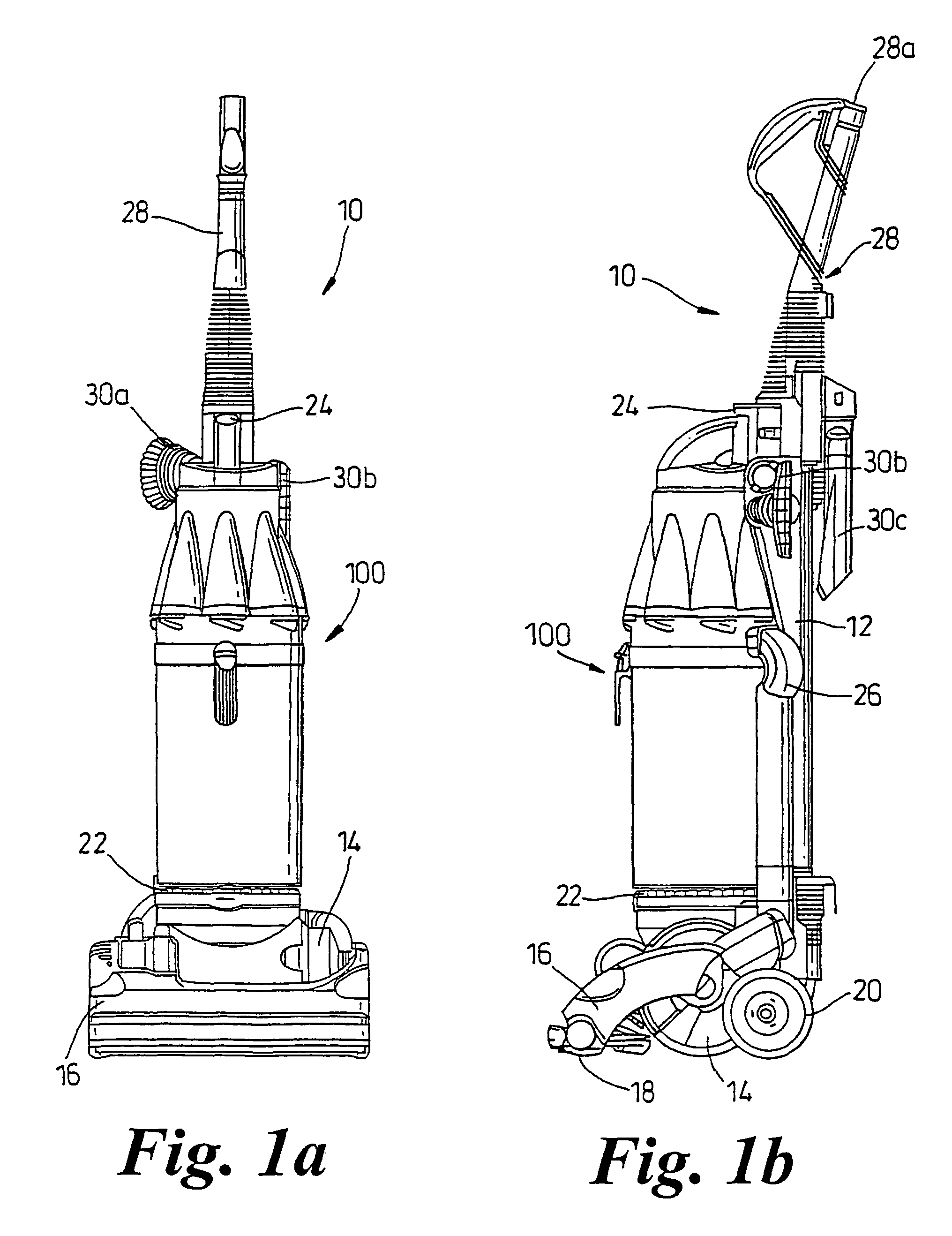
[0025]FIGS. 1a and 1b show a domestic vacuum cleaner 10 incorporating cyclonic separating apparatus according to the present invention. The vacuum cleaner 10 comprises an upstanding body 12 at a lower end of which is located a motor casing 14. A cleaner head 16 is mounted in an articulated fashion on the motor casing 14. A suction inlet 18 is provided in the cleaner head 16 and wheels 20 are rotatably mounted on the motor casing 14 to allow the vacuum cleaner 10 to be manoeuvered over a surface to be cleaned.

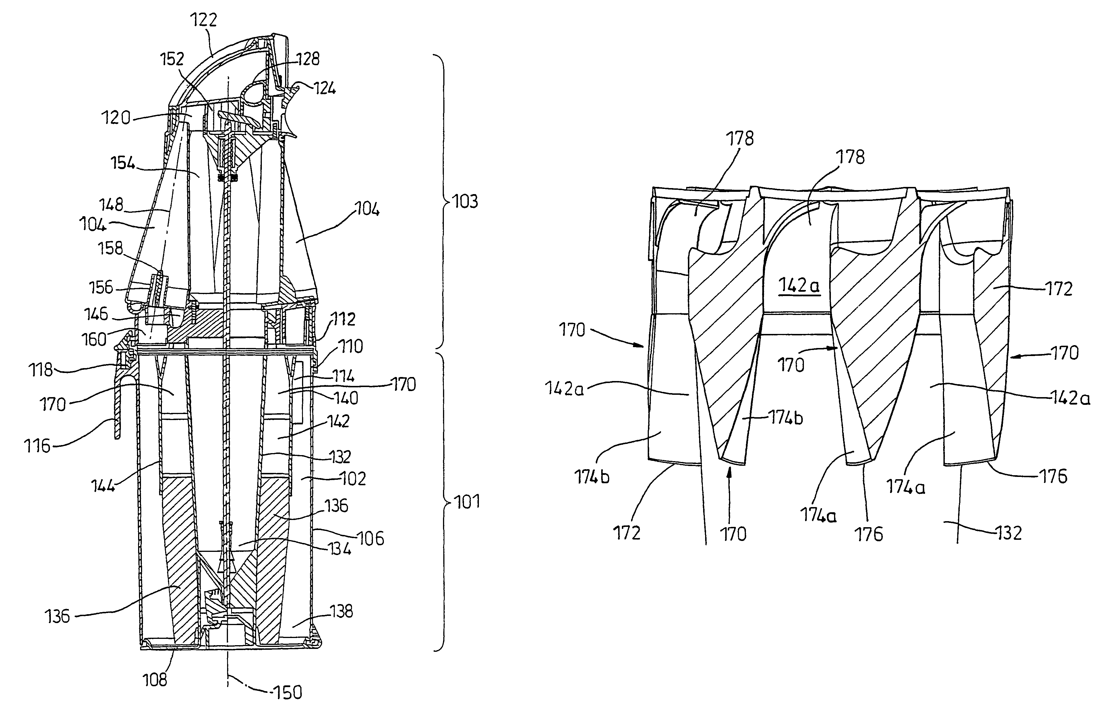
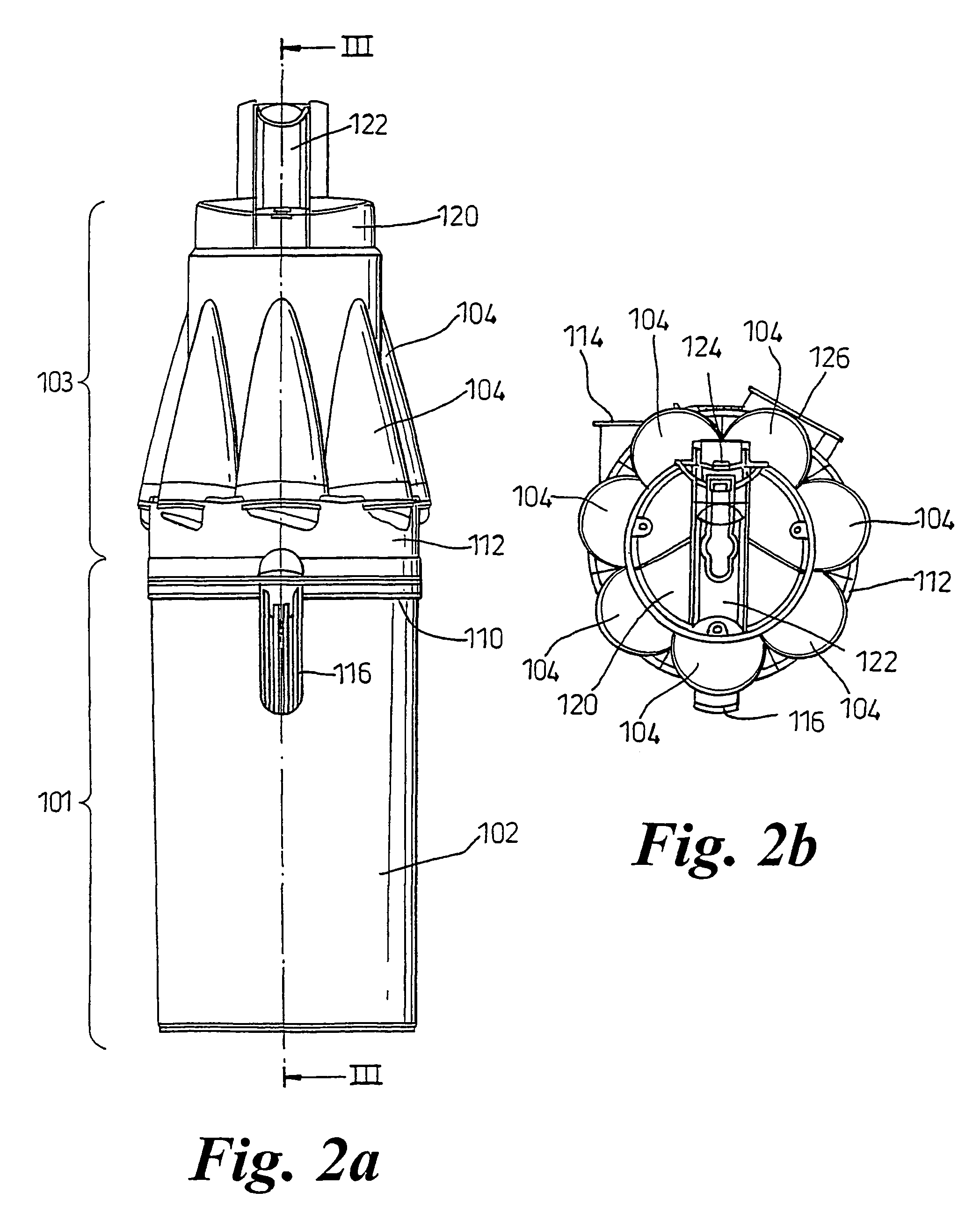
[0026]Cyclonic separating apparatus 100 is mounted on the upstanding body 12 above the motor casing 14. The cyclonic separating apparatus 100 is seated on a generally horizontal surface formed by a filter cover 22. The filter cover 22 is located above the motor casing 14 and provides a cover for a post-motor filter (not shown). The cyclonic separating apparatus 100 is also secured to the upstanding body 12 by means of a clip 24 located at the top of the cyclonic separating appar...


PUM

PropertyMeasurementUnit
radiusaaaaaaaaaa
areaaaaaaaaaaa
lengthaaaaaaaaaa

Abstract

The invention provides a cyclonic separating apparatus that includes a plurality of cyclones, each having an inlet and being arranged in parallel with one another, and a passageway arranged upstream of the cyclones for carrying an airflow to the inlets of the cyclones, wherein dividers are provided in the passageway for dividing the airflow within the passageway into a number of separate flowpaths, the number of flowpaths being equal to the number of cyclones, and wherein the cross-sectional area of each flowpath (142a), decreases along the direction of air flow. The invention also provides a method of operating a cyclonic separating apparatus (100) comprising a plurality of cyclones (104), each having an inlet and being arranged in parallel with one another, and a passageway (142) arranged upstream of the cyclones (104), the method comprising the steps of:(a) introducing a flow of dirt-laden air to the passageway (142); (b) dividing the flow of dirt-laden air into a plurality of airflow portions, the number of airflow portions being equal to the number of cyclones (104); and (c) reducing the cross-sectional area of each of the airflow portions in the direction of flow of the dirt-laden air.

Description

FIELD OF THE INVENTION[0001]The invention relates to cyclonic separating apparatus, particularly but not exclusively to cyclonic separating apparatus for use in vacuum cleaners. The invention also relates to a method of operating cyclonic separating apparatus of the aforementioned type.BACKGROUND OF THE INVENTION[0002]Cyclonic separating apparatus is well known and has uses in a wide variety of applications. Over the last decade or so, the use of cyclonic separating apparatus to separate particles from an airflow in a vacuum cleaner has been developed and introduced to the market. Detailed descriptions of cyclonic separating apparatus for use in vacuum cleaners are given in, inter alia, U.S. Pat. No. 3,425,192, U.S. Pat. No. 4,373,228 and EP 0 042 723. From these and other prior art documents, it can be seen that it is known to provide two cyclone units in series so that the airflow passes sequentially through at least two cyclones. This allows the larger dirt and debris to be extra...

Claims


Application Information

Patent Timeline
Patent Type & Authority Patents(United States)
IPC IPC(8): B01D45/12A47L9/16B04C5/06B04C5/28B04C7/00
CPCA47L9/1625A47L9/1641Y10S55/03
Inventor VUIJK, REMCO DOUWINUS
Owner DYSON TECH LTD
Why Eureka
Try Eureka