Alarm chip and use of the alarm chip

a technology of alarm chip and alarm chip, which is applied in the field of alarm chip, can solve the problems of inability to use the alarm chip, inconvenient use, and inability to meet the needs of the user, and achieve the effects of reducing the cost of use, and improving the safety of users

Inactive Publication Date: 2006-01-24
NORDAN
View PDF16 Cites 21 Cited by
  • Summary
  • Abstract
  • Description
  • Claims
  • Application Information

AI Technical Summary

Benefits of technology

[0019]The object of the invention is to provide an alarm chip which is preferably, but not necessarily, used in connection with shell-protection of buildings, installations or structures, in which, in use, the alarm chip is to give warning of a burglary attempt or an attempt at undesired entry into buildings, installations or structures. It should be possible for the alarm chip to be manufactured with small external dimensions, a small power consumption, preferably wireless signal transmission and at a competitive price. Besides, alarm chips arranged to one access opening each, should preferably allow independent connection to a central and / or external alarm unit / alarm system. Properly arranged to the access openings of a building, an installation or a structure, the alarm chip should be able to replace, completely or partially, known sensors or sensor techniques connected to an alarm unit or an alarm system, the above-mentioned drawbacks of known technique thereby being avoided or reduced.REALIZATION OF THE OBJECT
[0033]The use of an alarm chip according to the invention primarily has the effect that a building, installation or structure may be provided with shell-protection against burglary and undesired entry, in a simple and inexpensive way.
[0037]The alarm chip also transfers signals continuously to an alarm unit / alarm system, so that the user does not have to deal with possible activation or deactivation of the alarm chip or the alarm unit / alarm system arranged to the building, installation or structure, which is necessary, for example, when PIR-detectors and magnetic contact sensors are used.

Problems solved by technology

Many of the above-mentioned sensors utilize technology which is unsatisfactorily developed with respect to giving warning of burglary or other undesired entry into a building, installation or structure, or the technology / sensor is, at the present time, too expensive to be used for this purpose, for example the acoustic detector and the laser device.
In addition, some of these sensors, for example the low-energy oscillator, is difficult to calibrate, in the sense that it is difficult to distinguish real signals (alarm signals) from false signals (non-alarm signals), and that the sensors therefore often output alarm signals in connections where no burglary is committed or there is no undesired entry into a building, for example.
The passive infrared ray detector (the PIR detector) is by and large arranged, and is used, for protecting rooms in buildings, installations or structures, and this detector therefore does not provide any shell-protection for the building, installation or structure.
The use of magnetic contact sensors does not provide any protection against the breaking of glass.
In addition the most common devices for burglary protection, such as PIR detectors and magnetic contact sensors, entails the disadvantage that in the building, for example, junction boxes will have to be installed and wires must be laid for the power supply and / or signal transmission between the detector and the central and / or external alarm unit / alarm system arranged to the building.
This is particularly disadvantageous when such equipment is retrofitted into existing buildings, in which the cabling may often be labour-intensive and expensive.
Signal transmission through the existing power network of a building, installation or structure, possibly through an optical-fibre cable, is not arranged to be used in alarm installations at the present time, and it is particularly the use of an optical-fibre cable which seems, at the present time, too expensive to be used for this purpose.

Method used


Image

  • Alarm chip and use of the alarm chip
  • Alarm chip and use of the alarm chip

Examples


Embodiment Construction

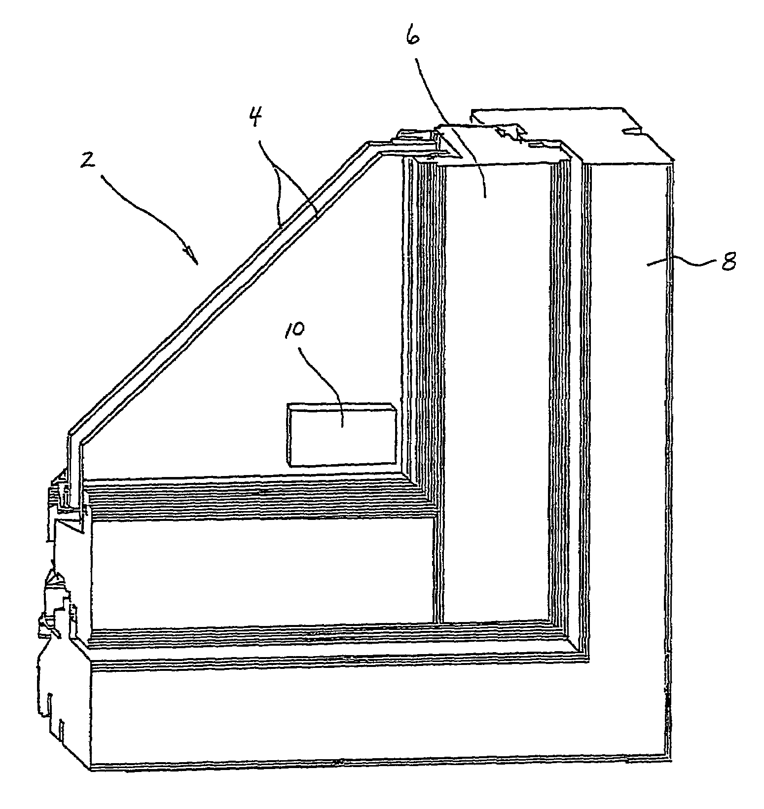
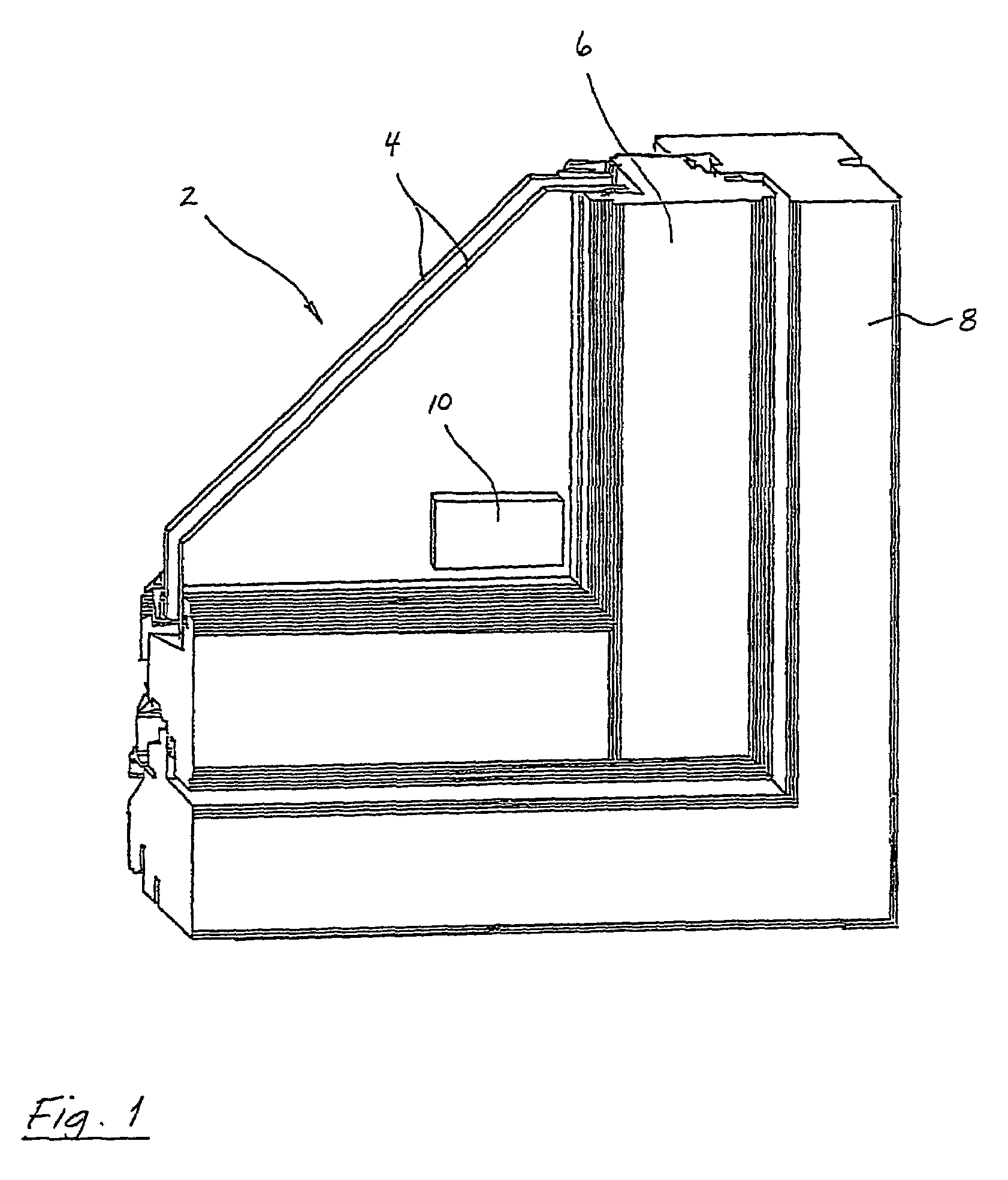
[0039]The appended drawn figure (FIG. 1) shows a perspective sectional view of a window 2 formed by double window glass 4 mounted in a window frame 6, the window frame 6 being disposed in an associated window casing 8 of a building not shown. Internally, the window glass 4 has an alarm chip 10 according to the invention attached thereto. The alarm chip 10 is provided with an accelerometer, not shown in the drawn figure, an ASIC electronic signal processing circuit not shown, incorporating i.a. an analogue-to-digital converter (ADC-component) and an electronic processor for processing digital acceleration data from the accelerometer. The alarm chip 10 is moreover provided with a radio frequency transmitter (RE transmitter) not shown, and a lithium battery, not shown, providing the alarm chip 10 with electrical power. The ASIC is arranged with software in the form of suitable algorithms, e.g. seismology-based algorithms, continuously processing incoming acceleration data produced by p...


PUM


Abstract

An alarm chip (10) and the use of the alarm chip (10) for giving warning of burglary or undesired entry into buildings, installations or structures, preferably by so-called shell-protection of the building, installation or structure, the alarm chip (10) detecting, by means of an associated accelerometer, motions / vibrations in the object to which the alarm chip (10) is fixedly arranged, the object being formed of e.g. a window (2), a door, possibly a frame or casing connected to the window (2) or door, wherein the motions / vibrations are converted by means of the accelerometer into an outgoing flow of acceleration values, which are further processed, by means of a processor in a signal processing circuit, in which, by means of algorithms, the acceleration values are recognized and separated into either output alarm signals or output non-alarm signals, and in which output signals may be coded / encrypted, so that each alarm chip (10) has i.a. a unique address and identity, and in which the signals are possibly also output in the form of signal pulses, preferably in a so-called pseudo-random order, the output signals being transmitted, preferably in a wireless manner, to at least one central and / or external alarm unit / alarm system arranged to the building, installation or structure.

Description

CROSS REFERENCE TO RELATED APPLICATION[0001]The present application is the U.S. national stage application of International Application PCT / NO01 / 00423, filed Oct. 22, 2001, which international application was published on May 2, 2002 as International Publication WO 02 / 3 5490. The International Application claims priority of Norwegian Patent Application 2000 5405, filed Oct. 26, 2000.FIELD OF THE INVENTION[0002]The invention relates to an alarm chip and the use of the alarm chip, the alarm chip preferably being used in connection with so-called shell-protection of buildings, installations or structures, wherein the shell-protection is preferably arranged to give warning of burglary or undesired entry into the building, installation or structure, but wherein the shell-protection possibly also has a preventive effect on possible intruders, the alarm chip preferably being positioned on windows or doors, possibly on or in associated frames or casings, of the building, installation or str...

Claims


Application Information

Patent Timeline
Patent Type & Authority Patents(United States)
IPC IPC(8): G08B13/00G08B13/04
CPCG08B13/04
Inventor RASMUSSEN, JOHN OLAV
Owner NORDAN
Why Eureka
Try Eureka