Recognition/anti-collision light for aircraft

a technology of anti-collision light and recognition/anti-collision light, which is applied in the direction of landing aids, lighting support devices, instruments, etc., can solve the problems of falling below the minimum intensity requirements and the light intensity of the flashtube gradually degrades with use, so as to extend the overall useful life of the light, extend the life of a single flashtube or multiple flashtubes

Inactive Publication Date: 2006-01-24
THE BF GOODRICH CO
View PDF26 Cites 12 Cited by
  • Summary
  • Abstract
  • Description
  • Claims
  • Application Information

AI Technical Summary

Benefits of technology

[0007]The present invention provides a recognition / anti-collision light including, in a preferred embodiment, two flashtubes and a control system that sequentially operates the two flashtubes in order to extend the overall useful life of the light. The invention also provides a technique for extending the life of a single flashtube or multiple flashtubes.
[0011]According to another aspect of the invention, a recognition light of an aircraft comprises a flashtube, a light detector positioned to detect light emitted from the flashtube, a monitor circuit connected to the light detector for measuring the intensity of the detected light and comparing the measured intensity with a reference value corresponding to a predetermined light intensity level, and a control circuit connected to the flashtube and monitor circuit for flashing the flashtube at a first power level and then at an increased power level when the measured intensity drops below the reference value, thereby to increase the intensity of the flashes emitted by the flashtube to above the predetermined light intensity level.
[0012]According to another aspect of the invention, a method for increasing the useful life of a recognition light of an aircraft comprises flashing a flashtube, monitoring the light output of the flashtube, comparing the measured light output of the flashtube with a reference value corresponding to a predetermined light intensity value, increasing the power delivered to the flashtube when the measured light output drops below the reference value, thereby to increase the intensity of the flashes emitted by the flashtube to above the reference value.
[0014]According to another aspect of the invention, a method for increasing the useful life of a recognition light comprises providing first and second lamps, operating the first lamp, monitoring a characteristic of the light output of the first lamp and providing a fail signal when the characteristic of the light output of the first lamp does not satisfy a specified criteria, and stopping operation of the first lamp and operating the second lamp in response to receipt of the fail signal.

Problems solved by technology

However, the light intensity of the flashtube gradually degrades with use over time and eventually falls below the minimum intensity requirements, thereby requiring servicing and / or replacement of the flashtube.

Method used


Image

  • Recognition/anti-collision light for aircraft
  • Recognition/anti-collision light for aircraft
  • Recognition/anti-collision light for aircraft

Examples


Embodiment Construction

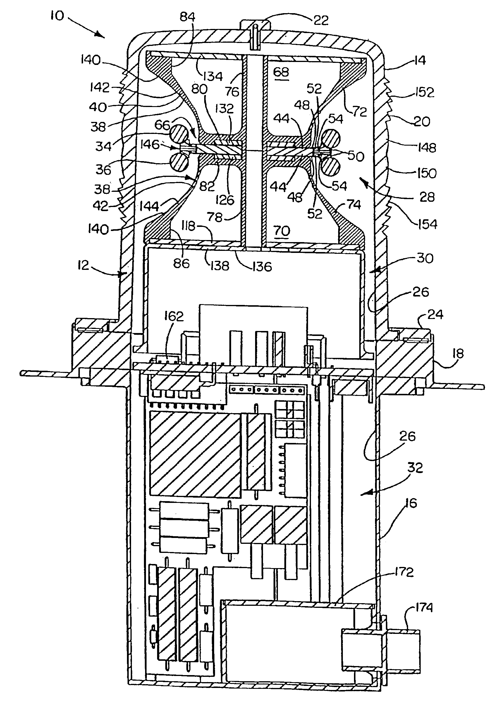
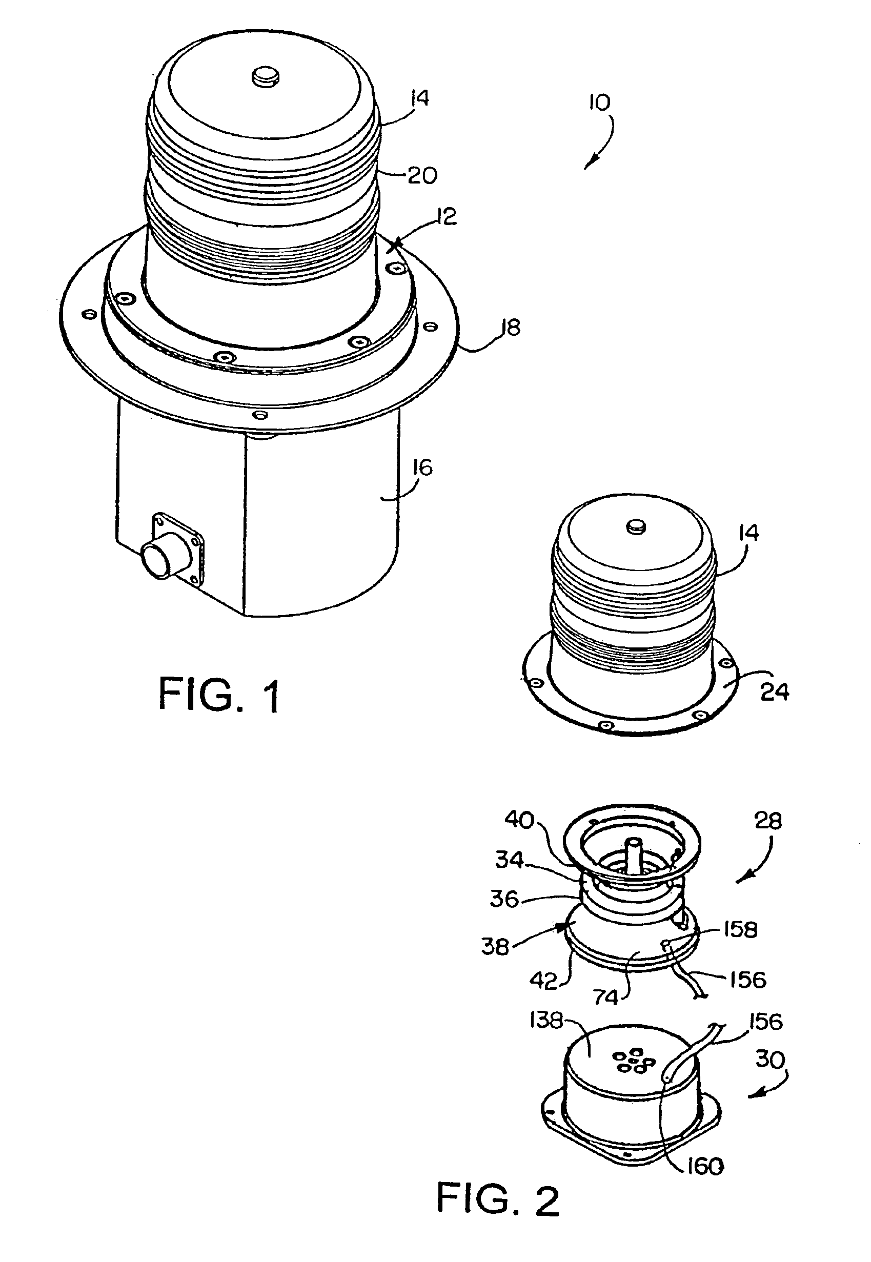
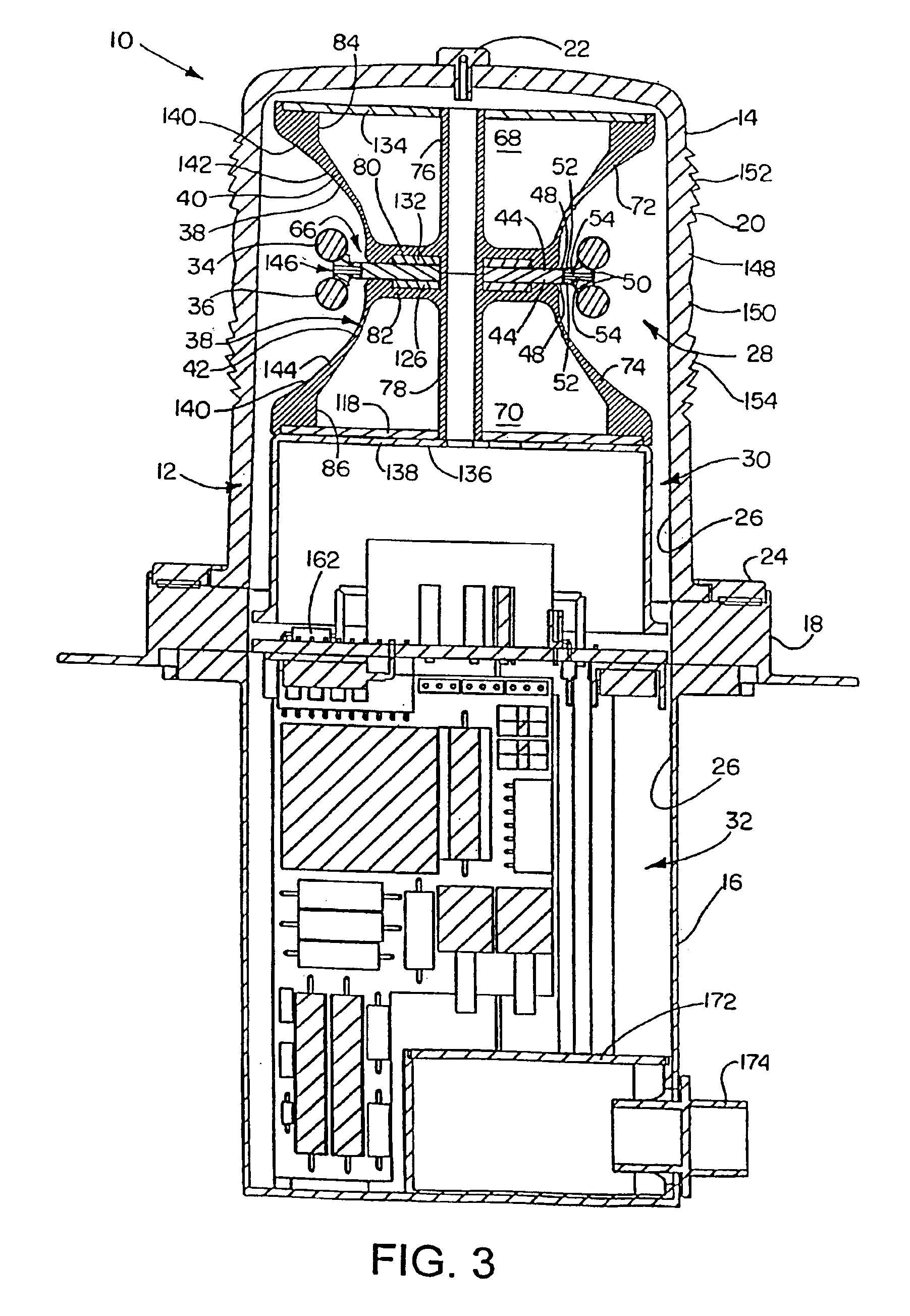
[0023]Referring now in detail to the drawings, and initially to FIGS. 1-3, a light constructed in accordance with the present invention is generally indicated at reference numeral 10. The light 10 was developed for use as an aircraft recognition / anti-collision light and is herein described chiefly in this context. However, those skilled in the art will appreciate that a light according to the invention will have other useful applications including but not limited to uses in other types of vehicles, in industrial applications, etc. It should be appreciated that such alternative applications are contemplated as falling within the scope of the present invention. It also should be appreciated that references herein to top and bottom, upper and lower, etc., are made in relation to the illustrated orientation of the light to describe positional relationships between components of the light and not by way of limitation, unless so indicated. Also, the terms “recognition” and “anti-collision...


PUM


Abstract

A recognition light includes a reflector having an axis and first and second annular semi-parabolic reflective surfaces which have respective focal points axially spaced apart from one another, and first and second annular lamps respectively disposed at the focal points. A cover surrounds the reflector and lamps and includes a lens for focusing the light along a plane perpendicular to the axis of the reflector, the lens including first and second Fresnel lens portions each including a convex lens and a prism lens, the convex lenses being disposed adjacent one another and transaxially aligned with the first and second lamps, respectively. A light detector detects light emitted from at least one of the lamps, a monitor circuit provides a fail signal when a characteristic of the light output of at least one of the lamps does not satisfy a specified criteria, and a control circuit first activates the first lamp and then the second lamp in response to receipt of the fail signal of the monitor circuit.

Description

[0001]This application is a divisional of U.S. patent application Ser. No. 09 / 933,935 filed on Aug. 21, 2001 now U.S. Pat. No. 6,642,856, U.S. patent application Ser. No. 09 / 187,495, filed Nov. 6, 1998, now U.S. Pat. No. 6,278,382, all of which are hereby incorporated herein by reference in their entirety.FIELD OF THE INVENTION[0002]The present invention relates to recognition / anti-collision lights and, more particularly, to a method and apparatus for extending the useful life of such lights and / or for detecting the failure of such lights.BACKGROUND OF THE INVENTION[0003]Recognition / anti-collision lights are used on aircraft to produce bright flashes of light readily visible to the human eye for improving recognition of the aircraft from the ground or from other aircraft. The FAA (Federal Aviation Administration) currently mandates that aircraft have such lights with an acceptable minimum effective light intensity of 100 or 400 candela (depending on the aircraft) when viewed within ...

Claims


Application Information

Patent Timeline
Patent Type & Authority Patents(United States)
IPC IPC(8): B64D47/06B60Q1/26F21V7/00F21V13/04
CPCB60Q1/2611B64D47/06F21V13/04F21V7/0058H05B41/30H05B41/38H05B41/46
Inventor DEMARCO, RALPH ANTHONYDRAVES, RAYMOND HENRYKIELBON, TIMOTHY SCOTTKNIGHT, TODD CHRISTOPHERPATEL, ANISH VIKRAMSTEPHENS, MERLE KEITH
Owner THE BF GOODRICH CO
Why Eureka
Try Eureka