Order-independent transparency rendering system and method

a transparency and rendering system technology, applied in the field of computer graphics, can solve the problems of difficult to achieve total visual realism, and difficult to implement transparency in graphics pipelines

Inactive Publication Date: 2006-01-24
NVIDIA CORP
View PDF7 Cites 87 Cited by
  • Summary
  • Abstract
  • Description
  • Claims
  • Application Information

AI Technical Summary

Benefits of technology

[0012]In a similar manner, the colored-transparency information relating to the at least one additional depth layer may be collected during at least one additional rendering pass. The at least one additional rendering pass may be taken from the same eye position from which a previous rendering pass is taken. A shadow-mapping feature may be enabled during the at least one additional rendering pass. Of course, the rendering passes may output depth layers in any form without the use of shadow-mapping techniques, and colored-transparency information may just as easily be collected from such rendering results. The depth information relating to the at least one additional depth layer may take the form of a shadow map to be used by subsequent rendering passes, and the colored-transparency information relating to the at least one additional depth layer may take the form of a texture map to be used for rendering the final scene with transparency.

Problems solved by technology

A fundamental difficulty in achieving total visual realism is the complexity of accurately representing real-world visual effects.
Transparency is particularly difficult to implement in a graphics pipeline due to many stringent requirements.
While per-primitive sorting may be handled by a central processing unit (CPU), it is impossible to implement per-fragment sorting in most dedicated graphics pipelines.
Moreover, any intersections among the objects / primitives frustrate the transparency calculations, since sorting order is not possible to establish at the primitive level.
Since object intersection is often prevalent, transparency can simply not be handled by most dedicated graphics hardware.
The foregoing requirements are frustrating for most graphics application developers, because the natural order of scene traversal in a graphics pipeline (i.e. usually one object at a time) rarely satisfies these requirements.
Objects can be complex, with their own transformation hierarchies.
Even more troublesome, with advanced dedicated graphics hardware, the vertices and fragments of objects may be altered by user-defined per-vertex or per-fragment operations.

Method used


Image

  • Order-independent transparency rendering system and method
  • Order-independent transparency rendering system and method
  • Order-independent transparency rendering system and method

Examples


Embodiment Construction

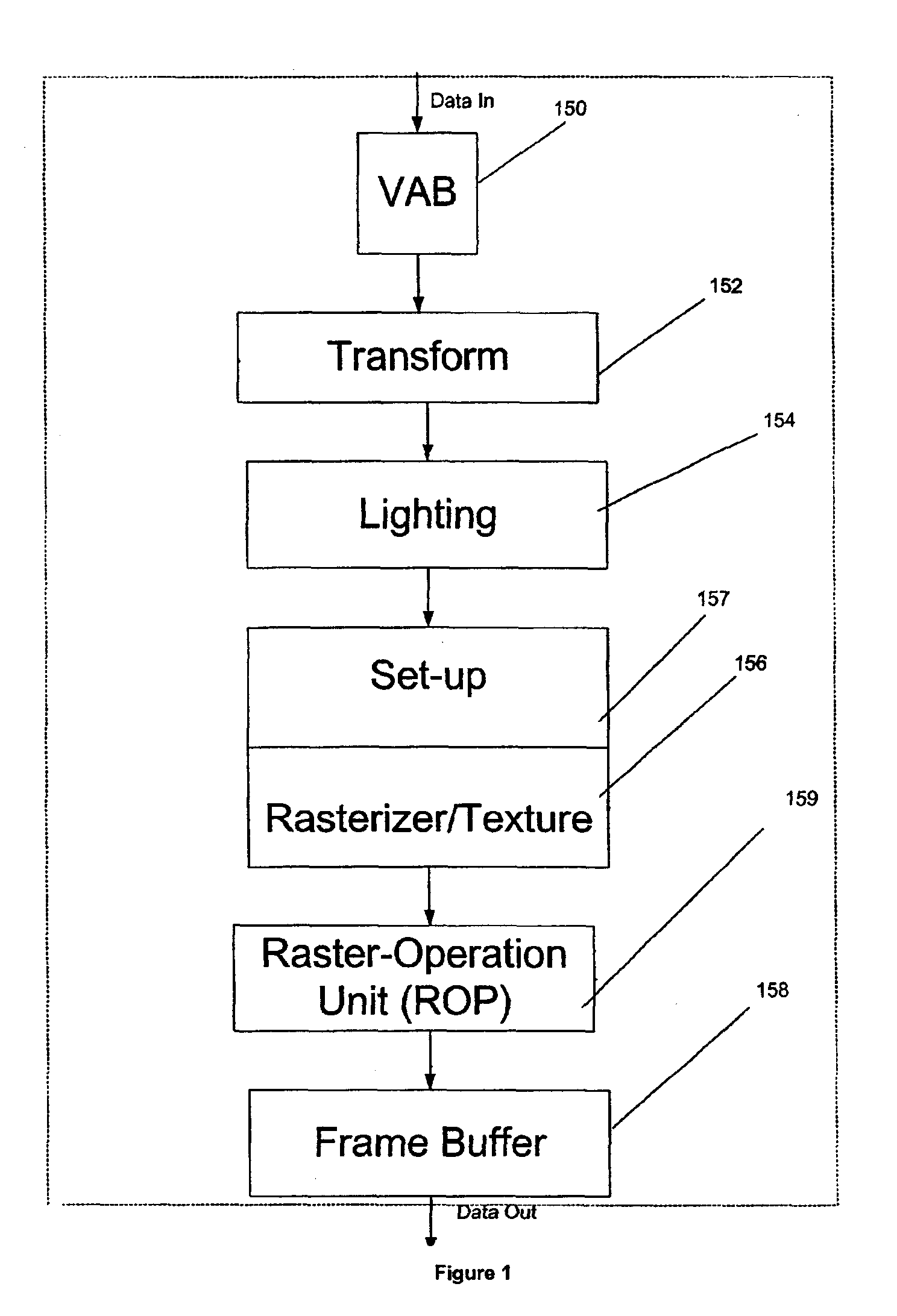
[0026]FIG. 1 is a system diagram illustrating the various components of one embodiment of the present invention. As shown, the present embodiment may be divided into a plurality of modules including a vertex attribute buffer (VAB) 150, a transform module 152, a lighting module 154, a rasterization / texturing module 156 with a set-up module 157, a raster-operation module (ROP) 159, and a frame buffer 158.

[0027]In one embodiment, each of the foregoing modules may be situated on a single semiconductor platform. In the present description, the single semiconductor platform may refer to a sole unitary semiconductor-based integrated circuit or chip. It should be noted that the term single semiconductor platform may also refer to multi-chip modules with increased connectivity which simulate on-chip operation, and make substantial improvements over utilizing a conventional CPU and bus implementation. Of course, the various modules may also be situated separately or in various combinations of...


PUM


Abstract

A system, method and computer program product are provided for transparency rendering in a graphics pipeline. Initially, colored-transparency information is collected from a plurality of depth layers (i.e. colored-transparency layers, etc.) in a scene to be rendered. The collected colored-transparency information is then stored in memory. The colored-transparency information from the depth layers may then be blended in a predetermined order.

Description

RELATED APPLICATION(S)[0001]The present application is related to co-pending applications entitled “SYSTEM AND METHOD FOR USING AND COLLECTING INFORMATION FROM A PLURALITY OF DEPTH LAYERS” filed concurrently herewith under Ser. No. 09 / 945,444 and naming the same inventors as the present application, and “SYSTEM AND METHOD FOR DUAL-DEPTH SHADOW MAPPING” filed concurrently herewith under Ser. No. 09 / 944,990 and naming the same inventors as the present application, which are each incorporated herein by reference in their entirety.FIELD OF THE INVENTION[0002]The present invention relates to computer graphics, and more particularly to rendering at least partially transparent objects in a graphics pipeline.BACKGROUND OF THE INVENTION[0003]A major objective in graphics rendering is to produce images that are so realistic that the observer believes the image is real. A fundamental difficulty in achieving total visual realism is the complexity of accurately representing real-world visual eff...

Claims


Application Information

Patent Timeline
Patent Type & Authority Patents(United States)
IPC IPC(8): G09G5/02
CPCG06T15/503G06T15/04
Inventor EVERITT, CASS W.BASTOS, RUI M.KILGARD, MARK J.
Owner NVIDIA CORP
Why Eureka
Try Eureka