Container inspection machine

a container and inspection machine technology, applied in the field of glass container inspection systems, can solve the problems of adding substantial cost to the system by each camera

Active Publication Date: 2006-01-24
EMHART GLASS SA
View PDF3 Cites 9 Cited by
  • Summary
  • Abstract
  • Description
  • Claims
  • Application Information

AI Technical Summary

Problems solved by technology

More and more of these inspections are conducted using camera technology and each camera adds substantial cost to the system.

Method used


Image

  • Container inspection machine
  • Container inspection machine

Examples


Embodiment Construction

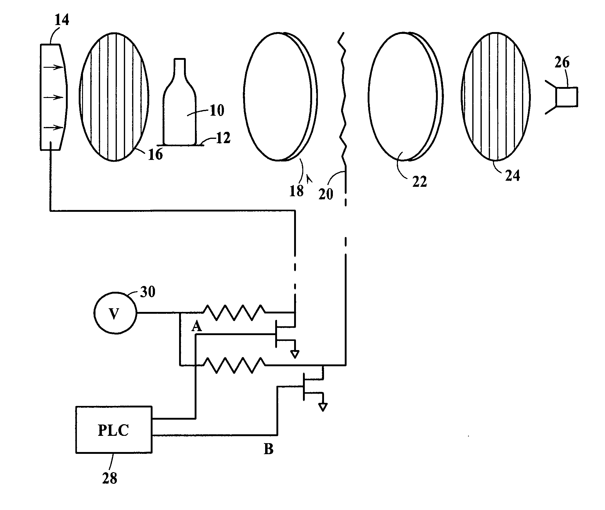
[0007]FIG. 1 shows a bottle 10 being conveyed through an inspection station of an inspection machine by a conveyor 12. At a first polarizer 16 and this polarized light this inspection station, a source of light 14 passes through passes through the bottle in a direction perpendicular to the axis of the bottle. The light then passes through a first electrode surface 18, a FLC 20 (ferroelectric liquid crystal), a second electrode surface 22, a second polarizer 24 which has the same polarity as the first polarizer 16, and images on the imaging surface of the camera 26.

[0008]The operation of the electrode surfaces is controlled by outputs from a PLC 28 which activate either A or B to apply voltage V 30 to either the first or second electrode surfaces. When A is activated the camera will illuminated with bright polarized light (the electrode surfaces and the FLC define the same polarity as the first and second polarizers) so that the side wall of the bottle can be inspected and when B is ...


PUM

PropertyMeasurementUnit
temperatureaaaaaaaaaa
ferroelectricaaaaaaaaaa
temperatureaaaaaaaaaa

Abstract

An inspection system completes two inspections with a single camera. In one inspection polarized light illuminates the side wall of a bottle, passes through a pair of electrode surfaces on either side of a ferroelectric crystal which do not change the polarity and passes through a polarizer to image on the camera. In a second inspection the polarized light is rotated 90° by the same structure so that only light rotated as a result of stress in the bottle passes through the polarizer and images on the camera as a defect.

Description

[0001]The present invention relates to machines which have a camera based inspection system for inspecting bottles for defects.BACKGROUND OF THE INVENTION[0002]Machines for inspecting glass bottles conduct a great variety of inspections. More and more of these inspections are conducted using camera technology and each camera adds substantial cost to the system.OBJECT OF THE INVENTION[0003]It is an object of the present invention to provide a system for inspecting glass containers which will enable a single camera to carry out two inspections.[0004]Other objects and advantages of the present invention will become apparent from the following portion of this specification and from the accompanying drawings which illustrate, in accordance with the mandate of the patent statutes, a presently preferred embodiment incorporating the principles of the invention.BRIEF DESCRIPTION OF THE DRAWINGS[0005]FIG. 1 is a schematic illustration of an inspection machine made in accordance with the teach...

Claims


Application Information

Patent Timeline
Patent Type & Authority Patents(United States)
IPC IPC(8): H04N7/18G01N21/21G01N21/90G02F1/13G02F1/141
CPCG01N21/90G01N21/21
Inventor FURNAS, WILLIAM J.
Owner EMHART GLASS SA
Why Eureka
Try Eureka