Magnetic tape and manufacturing method thereof, and servo writer and servo write method
a technology of magnetic tape and manufacturing method, applied in the field of magnetic tape, can solve the problems of not being able to identify the position of a data track in a lateral direction of a magnetic tape, and taking time to access each data track,
- Summary
- Abstract
- Description
- Claims
- Application Information
AI Technical Summary
Benefits of technology
Problems solved by technology
Method used
Image
Examples
first embodiment
[0036]Next, the magnetic tape MT of the present invention, where the DC magnetization regions LZ1 to LZ5 and the servo signals S1 to S5 are written as above, will be described, referring to FIG. 3A, and FIGS. 4A and 4B.
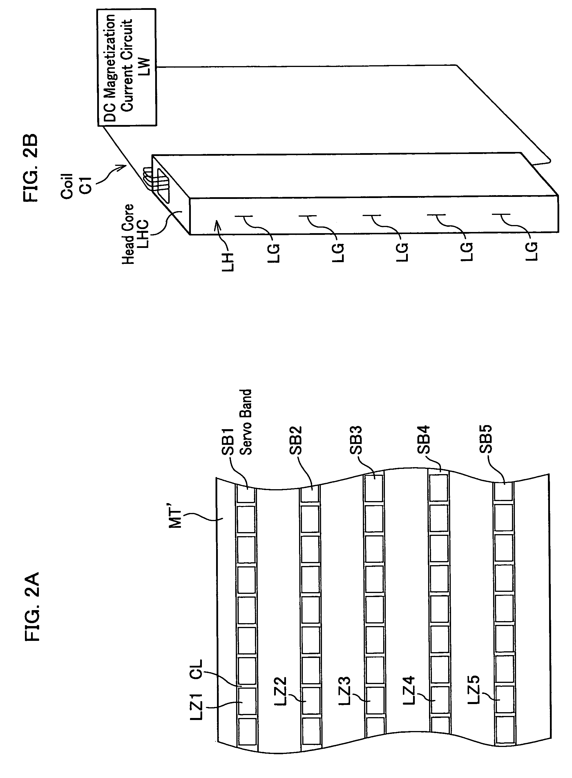
[0037]As shown in FIG. 3A, in the magnetic tape MT along longitudinal directions thereof are provided five servo bands SB1 to SB5 at an equal distance in a lateral direction of the magnetic tape MT, and between these servo bands are provided data bands DB1 to DB4. And on each of the servo bands SB1 to SB5 are, as shown in FIGS. 2A and 3A, formed the DC magnetization regions LZ1 to LZ5 that are discontinuously magnetized in one direction with opening the distance CL. Within each of the DC magnetization regions LZ1 to LZ5 is written each of the predetermined servo signals S1 to S5 for performing tracking-control of a magnetic head.
[0038]The servo signals S1 to S5 are, as in FIG. 4A where nothing but the servo band SB1 is shown in enlargement, configured of sub-frames 1 ...
second embodiment
[0041]In addition, FIG. 5A is a drawing showing the magnetization intensity of the DC magnetization regions LZ1 to LZ5 related to the present invention; FIG. 5B is a drawing showing the recording magnetization intensity of servo signals S1 to S5 (linear patterns L1 to L8) of each of the DC magnetization regions LZ1 to LZ5.
[0042]In this magnetic tape along longitudinal directions thereof, same as in the magnetic tape MT related to the first embodiment shown in FIG. 3A, are provided five servo bands SB1 to SB5 at an equal distance in a lateral direction of the magnetic tape, and between these servo bands B1 to B5 are provided the data bands DB1 to DB4. And on each of the servo bands SB1 to SB5 are, same as in the magnetic tape MT related to the first embodiment shown in FIG. 3A, formed the DC magnetization regions LZ1 to LZ5 that are discontinuously magnetized in one direction with opening the distance CL. It is same as in the magnetic tape MT related to the first embodiment that: wit...
PUM
| Property | Measurement | Unit |
|---|---|---|
| magnetic | aaaaa | aaaaa |
| DC magnetization | aaaaa | aaaaa |
| DC magnetization intensity | aaaaa | aaaaa |
Abstract
Description
Claims
Application Information
 - R&D
- Intellectual Property
- Life Sciences
- Materials
- Tech Scout
- Unparalleled Data Quality
- Higher Quality Content
- 60% Fewer Hallucinations
Browse by: Latest US Patents, China's latest patents, Technical Efficacy Thesaurus, Application Domain, Technology Topic, Popular Technical Reports.
© 2025 PatSnap. All rights reserved.Legal|Privacy policy|Modern Slavery Act Transparency Statement|Sitemap|About US| Contact US: help@patsnap.com


