Hybrid capillary cooling apparatus

Active Publication Date: 2006-01-31
ADVANCED COOLING TECH
View PDF10 Cites 83 Cited by
  • Summary
  • Abstract
  • Description
  • Claims
  • Application Information

AI Technical Summary

Benefits of technology

[0011]Vapor pressure is also used to drive the movement of condensed liquid from the condenser to the reservoir from which the pump draws the liquid supplied to the evaporator. The reservoir is sub-cooled to a temperature below that of the condenser. This assures that vapor pressure differential between them will move the liquid from the condenser to the reservoir. In one embodiment of the present invention a thermoelectric cooler is used to cool the reservoir by moving heat from the reservoir to the evaporator. The reservoir can also be subc

Problems solved by technology

However, the significant difference between hybrid cooling loops and heat pipes and loop heat pipes arises in the mechanisms for returning the condensed liquid from the condenser to the evaporato

Method used


Image

  • Hybrid capillary cooling apparatus
  • Hybrid capillary cooling apparatus
  • Hybrid capillary cooling apparatus

Examples


Embodiment Construction

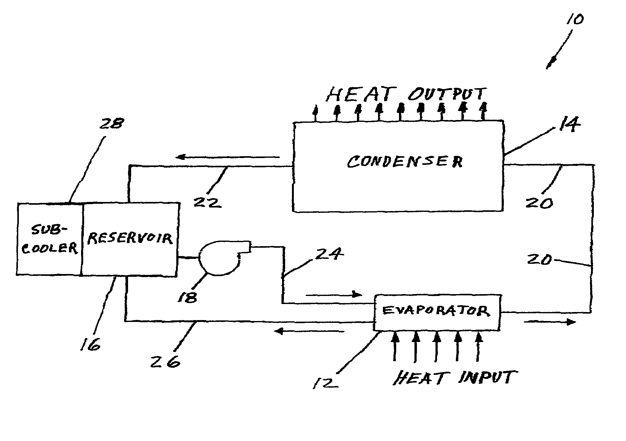
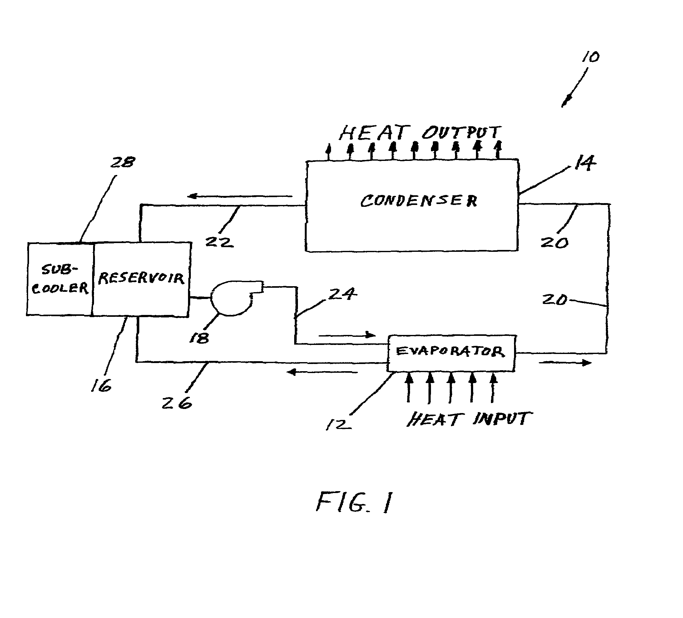
[0019]FIG. 1 is a simplified schematic block diagram of hybrid loop cooler 10 which includes four major components, evaporator 12, condenser 14, liquid reservoir 16, and pump 18. As with any vapor driven heat transfer device, all four components and all the tubing connecting them are sealed from the outside environment, and all non-condensable gases are evacuated from the entire enclosed volume.

[0020]In operation of hybrid loop 10 shown in FIG. 1, heat is transferred into evaporator 12, where liquid within an internal wick is vaporized and creates vapor at a pressure which depends upon the temperature of the heat source. The vapor pressure pushes the vapor from evaporator 12 through vapor lines 20 into condenser 14 where the vapor condenses because the temperature of condenser 14 is held down by a heat sink (not shown) that is cooled by an external device such as a radiator or a conduction or convection cooling device. The resulting condensate, the condensed liquid, then moves throu...


PUM


Abstract

The apparatus is a hybrid cooler which includes one loop within which a heated evaporator forms vapor that moves to a condenser because of the vapor pressure which also drives the liquid condensate from the condenser to a liquid reservoir. A second loop is powered by a mechanical pump that supplies liquid from the reservoir to the evaporator and the second loop also returns excess liquid not vaporized to the reservoir. An optional reservoir cooler can be used to assure that the reservoir temperature and vapor pressure are always lower that the temperatures and pressures of the evaporator and condenser.

Description

BACKGROUND OF THE INVENTION[0001]This invention deals generally with heat transfer and more particularly with a high performance passive two phase cooling loop that is supplemented by a secondary loop with a mechanical pump for moving liquid to the evaporator and excess liquid back to a reservoir.[0002]Future space and terrestrial systems will depend heavily on thermal management technologies that are capable of high performance in compact configurations that are not presently available and for use in environments that are much harsher than those to which the available technology has been subjected. For example, one proposed pulsed laser communication system has a peak power of 4 kW, and present cooling techniques limit the design to a duty cycle of only 0.025%. Continuing trends of increasing heat generated by such equipment and reduced package size will soon result in the requirement for heat removal capabilities exceeding 100 W / cm2. Furthermore, when used for space vehicles such ...

Claims


Application Information

Patent Timeline
IPC IPC(8): F25B21/02
CPCB64G1/50F25B21/02F25B25/00F28D15/046F28D15/0266F25B39/02F25B2339/021
Inventor ZUO, JONSARRAF, DAVID
Owner ADVANCED COOLING TECH
Why Eureka
Try Eureka