Torque wrench

a torque wrench and torque technology, applied in the field of torque wrenches, can solve the problems of reducing the intended function of overload protection at the handle end, affecting the service life of torque wrenches, and causing the ratchet to wear more and more, and achieve the effect of improving efficiency

a torque wrench and torque technology, applied in the field of torque wrenches, can solve the problems of reducing the intended function of overload protection at the handle end, affecting the service life of torque wrenches, and causing the ratchet to wear more and more, and achieve the effect of improving efficiency

US6990877B1Active Publication Date: 2006-01-31WU WUN SIN

Image

  • Torque wrench
  • Torque wrench
  • Torque wrench

Examples


Embodiment Construction

[0021]The features and the advantages of the present invention will be more readily understood upon a thoughtful deliberation of the following detailed description of a preferred embodiment of the present invention with reference to the accompanying drawings.

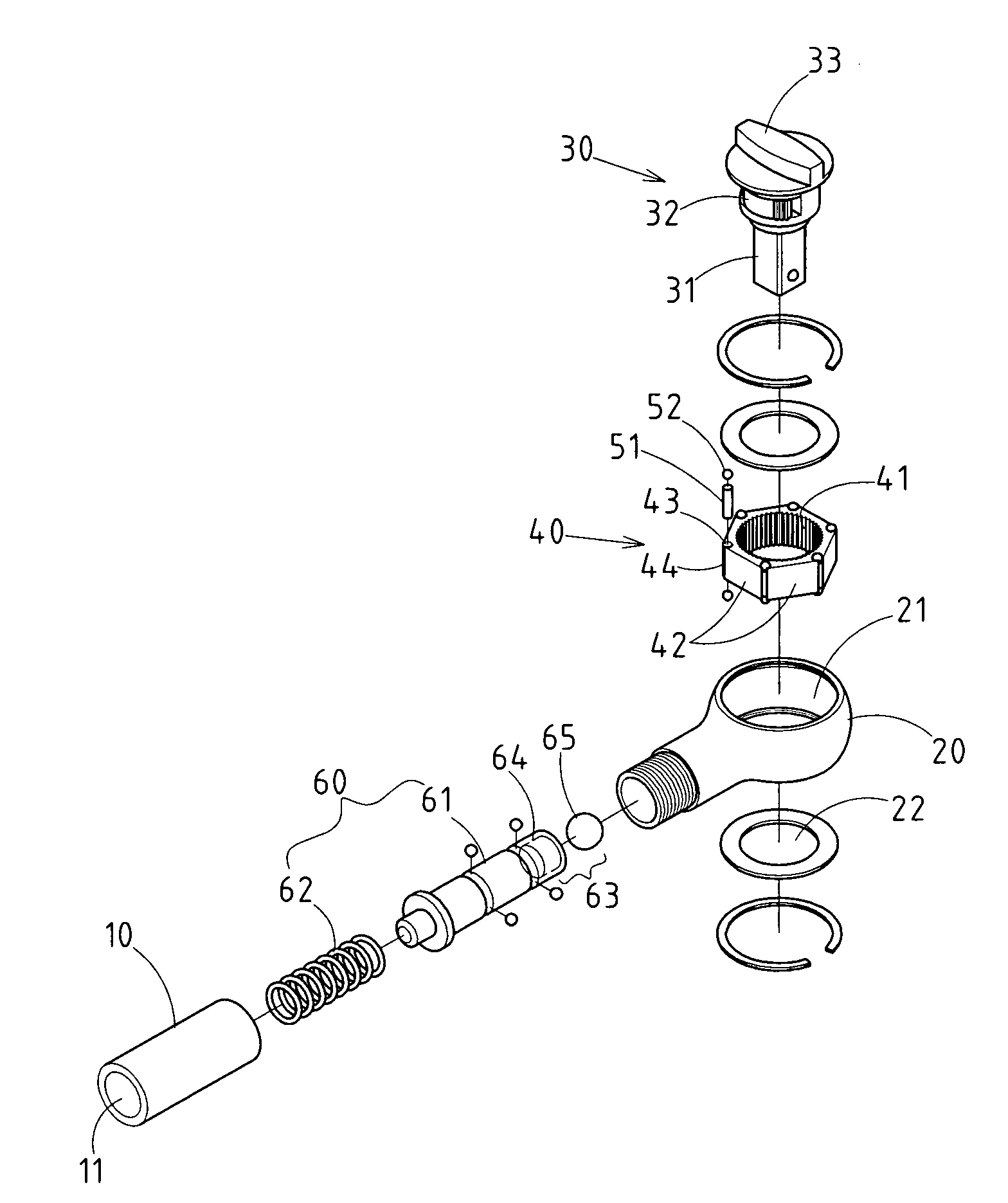
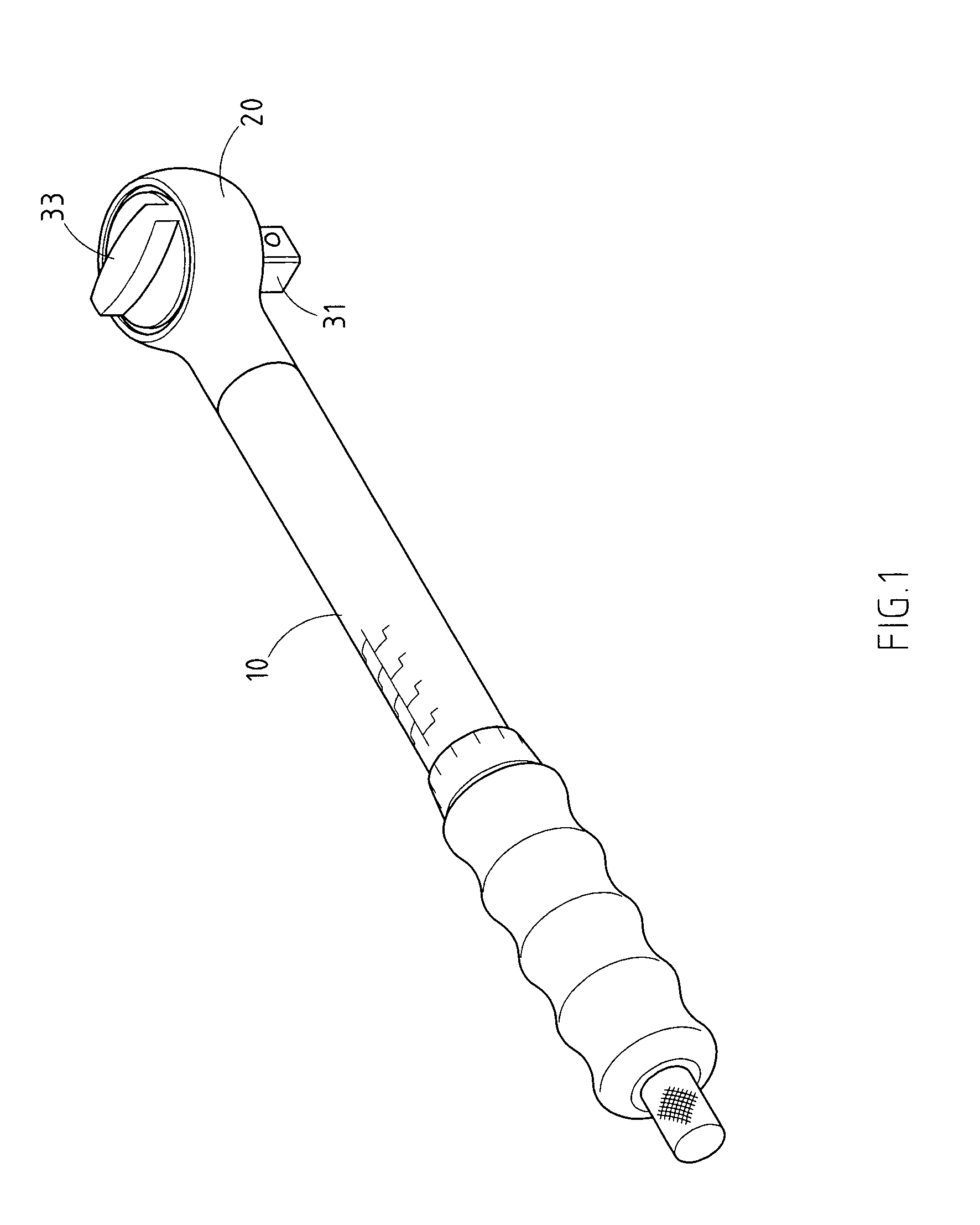
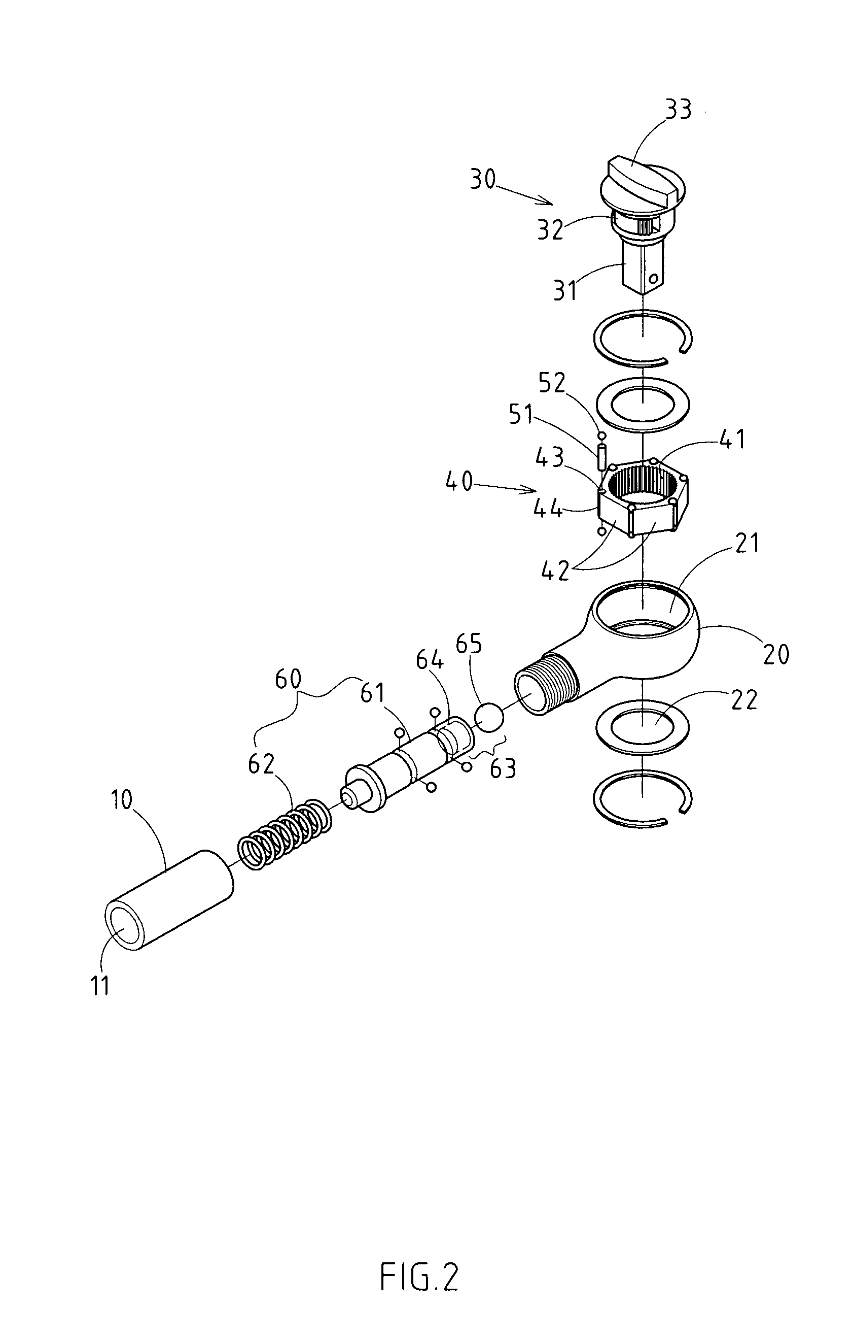
[0022]As shown in FIGS. 1–4, there is a torque wrench embodied in the present invention.

[0023]The invention has a pressure handle 10, which is provided internally with a hollow hole 11.

[0024]The invention also has a sheath end 20, which is provided at one side of the pressure handle 10, and equipped with an assembly groove 21. The assembly groove is provided with a threaded hole 22 at the bottom, while one side of the assembly groove 21 opposite to the pressure handle 10 is connected to the hollow hole 11.

[0025]There is also a directional brake module 30, which is mounted within the assembly groove 21 of the sheath end, being comprised of a sheath rod 31, a brake section 32 and a control unit 33. The sheath rod 31, generally des...


PUM


Abstract

A torque wrench includes a pressure handle, a sheath end, a directional brake module, an overload movement ring, rolling rods, rolling beads and spring bolsters. The overload movement ring is provided between the brake section of directional brake module and the assembly groove of sheath end. The interior of the overload movement ring is designed with a circular tooth rim for the articulation / brake of the brake section of directional brake module, whereas the exterior is designed with a polygon. Moreover, a containment groove is provided at the intersection of various surfaces to accommodate the rolling rod and rolling bead, thus the outer flank of various rolling rods and rolling beads will protrude the aperture of the containment groove, and then keep in close contact with the wall of the assembly groove. One surface of the overload movement ring is supported and braked by the movable shore of spring bolster.

Description

RELATED U.S. APPLICATIONS[0001]Not applicable.STATEMENT REGARDING FEDERALLY SPONSORED RESEARCH OR DEVELOPMENT[0002]Not applicable.REFERENCE TO MICROFICHE APPENDIX[0003]Not applicable.FIELD OF THE INVENTION[0004]The present invention relates generally to a torque wrench, and more particularly to a torque wrench which comprises improved structure of overload movement.BACKGROUND OF THE INVENTION[0005]To avoid structural damage from excessive external force, the torque wrench is typically designed with overload protective measures. So, in case where the applied force of the pressure handle exceeds the preset value, the sheath end and pressure handle will move alternatively, thus preventing structural damage arising from continuous application of force by the user. With regard to a conventional structure of overload protective measure, a ratchet ring is typically mounted within the groove at the sheath end of torque wrench. The interior of the ratchet ring is provided with a supporting s...

Claims


Application Information

Patent Timeline
31 Jan 2006
Publication
US6990877B1
IPC
B25B13/46; B25B23/143
CPC
B25B23/1427; B25B13/465
Inventors
WU, WUN-SIN