Movable quilting work area system and method

a work area and quilting technology, applied in the field of quilting devices, can solve the problems of requiring a considerable amount of space to set up and use, the quilting frame is expensive, and the hand stitching has become less common, so as to facilitate the fore and aft lateral movement, increase the lateral pattern coverage, and maintain the effect of tension

Inactive Publication Date: 2006-01-31
MCMUFFIN & SNUFFLES
View PDF5 Cites 38 Cited by
  • Summary
  • Abstract
  • Description
  • Claims
  • Application Information

AI Technical Summary

Benefits of technology

[0023]In view of the foregoing, it is among the objects and advantages of the present invention to provide an affordable and user-friendly apparatus to allow the sewing of patterns larger than the throat depth of a sewing machine. It is also an object / advantage of the present invention to be usable with a wide variety of existing and future hobby and professional quilting frames. It is also an object / advantage of the present invention to be usable with a wide variety of existing and future hobby and professional sewing machines of a wide range of throat depths. It is also an object / advantage of the present invention to provide automatic, continuous operation whereby the take-up roller is moved automatically without user initiation to allow the sewing of patterns larger than the throat depth of a sewing machine. It is also an object / advantage of the present invention to provide a lightweight apparatus which is portable and can be used with portable quilting frames. It is also an object / advantage of the present invention to be usable with a wide variety of computer controlled, manually controlled (free hand), or X-Y template-guided sewing machine carriages provided by the manufacturers of hobby and professional quilting frame or by third parties.
[0024]Consistent with the foregoing objects, and in accordance with the present invention as embodied and broadly described herein, a method and apparatus are disclosed in the presently preferred embodiment of the present invention comprising a powered take-up roller journaled in one or more movable motorized carriage assemblies (and where only one motor is used on one end of the take-up roller, an opposed movable take-up roller idler carriage assembly); two opposed end plates having tracks or sliding surfaces mounted thereon receiving the roller carriage assemblies; a sensor system for initiating take-up roller rotation, an automatic tension system; control electronics for use with a quilting frame of any dimension; and a sewing machine of any throat depth.
[0025]In addition, the inventive VSA system can be integrated with quilting application software to provide PC operated quilting with automatic VSA. The apparatus and method provides automatic, powered fore and aft (Forward / Backward) lateral movement of the quilting frame's takeup roller while simultaneously rotating the take-up roller clockwise or counter-clockwise to allow take-up or payout (furling or unfurling) of fabric layers to provide a movable working area, called a Variable Sewing Area or VSA. The VSA permits increased lateral pattern coverage by means of conventional sewing machine carriages used with the quilting frame, while tension is simultaneously maintained on the fabric layers stretched between the take-up roller and the payout roller or rollers. The prior art restriction on pattern depth caused by the combination of a fixed takup roller and limited sewing machine throat depth is substantially reduced or eliminated.
[0026]In one presently preferred embodiment of the present invention, the take-up roller may be configured in sections or telescoping to provide a wide range of quilt widths. In the alternative, it may be of any desired fixed length. In any of these configurations, it may be square, round, elliptical or polygonal in cross-section. The take-up roller in any such configuration is attached at each end to a movable carriage assembly. In the optional embodiment where a motor is used only at one end, the other end of the take-up roller is mounted to a movable idler carriage assembly.
[0027]A tension device system is used at both take-up roller carriages to provide Backward tension on the movable motor and optional movable idler assembly carriages to maintain constant tension on the fabric layer or layers stretched between the fabric supply (payout) rollers of the quilting frame and the take-up roller. Tracks, rails or sliding surfaces may be used to facilitate the fore and aft lateral movement of the movable motor carriage assembly and the idler assembly at each end of the take-up roller, independent of both the motorized rotation of the take-up roller and of the tensioning device(s). The corresponding tracks, rails or sliding surfaces preferably are mounted on each opposed end plate of the apparatus and preferably include at least a Back stop, and optionally also a Forward Stop, to limit movement of the take-up roller beyond an appropriate working range. In the alternative, with simple reversal of parts, the tracks may be on the take-up roller motorized carriage and the idler carriage, and the wheels or other sliding members may be mounted on the end plates.
[0028]Continuing with a presently preferred embodiment, the movable motor carriage assembly comprises a direct current reversible motor connected to a gear box with a projecting shaft (available in the marketplace as a complete pre-assembled unit, commonly known as gear head motors). Wheels are attached to the gear head motor assembly unit in an operative geometric array using commonly available fasteners; the wheels are preferably grooved to receive the guide tracks or rails secured to the end plates. Each end of the take-up roller is attached to the respective Left or Right motor assembly output shaft, optionally but preferably by means of a coupling tube which fits over the gear box output shaft and is locked in place by means of a set screw, removable pin, or the like. The other end of the coupling tube slides into or over the tubular take-up roller and is locked in place by means of a set screw or a removable pin.

Problems solved by technology

As the making of quilts has become more hobby oriented, hand stitching has become less common because of the lack of time by hobbyists.
Such professional quilting frames were, and still are, very expensive and require a considerable amount of space to set up and use.
Home sewing machines, however, have very limited throat depth—on the order of 6–9 inches.
Thus, both hobby quilting frames and professional quilting frames are restricted to sewing patterns having a lateral dimension no larger than the throat depth of the sewing machine, less the amount of space occupied by the take-up roller (including the fabric layers and batting rolled onto the take-up roller).
This is a major problem for, and complaint of, owners of present hobby quilting frames.
This limited working depth problem has caused many potential buyers of hobby quilting frames to not purchase such a product.
However, motorizing fixed rollers does not allow for sewing larger patterns because the working depth and area is still restricted by a combination of the fixed spatial relationship of the rollers and the throat depth of the sewing machine.
In addition, roller motors and associated control electronics of automated commercial machines are expensive and are normally used only for production of simplistic patterned quilts.
They are not available for, and do not address, the needs of the hobby-quilt artist, particularly in cases of large, complex or intricate artistic patterns.
Although professional quilting machines use sewing machines with deeper throats, up to 30 inches, the payout and take-up rollers are of a fixed nature and thus only permit sewing patterns limited by that throat depth.

Method used


Image

  • Movable quilting work area system and method
  • Movable quilting work area system and method
  • Movable quilting work area system and method

Examples


Embodiment Construction

[0053]The following detailed description illustrates the invention by way of example, not by way of limitation of the scope, equivalents or principles of the invention. This description will clearly enable one skilled in the art to make and use the invention, and describes several embodiments, adaptations, variations, alternatives and uses of the invention, including what is presently believed to be the best modes of carrying out the invention.

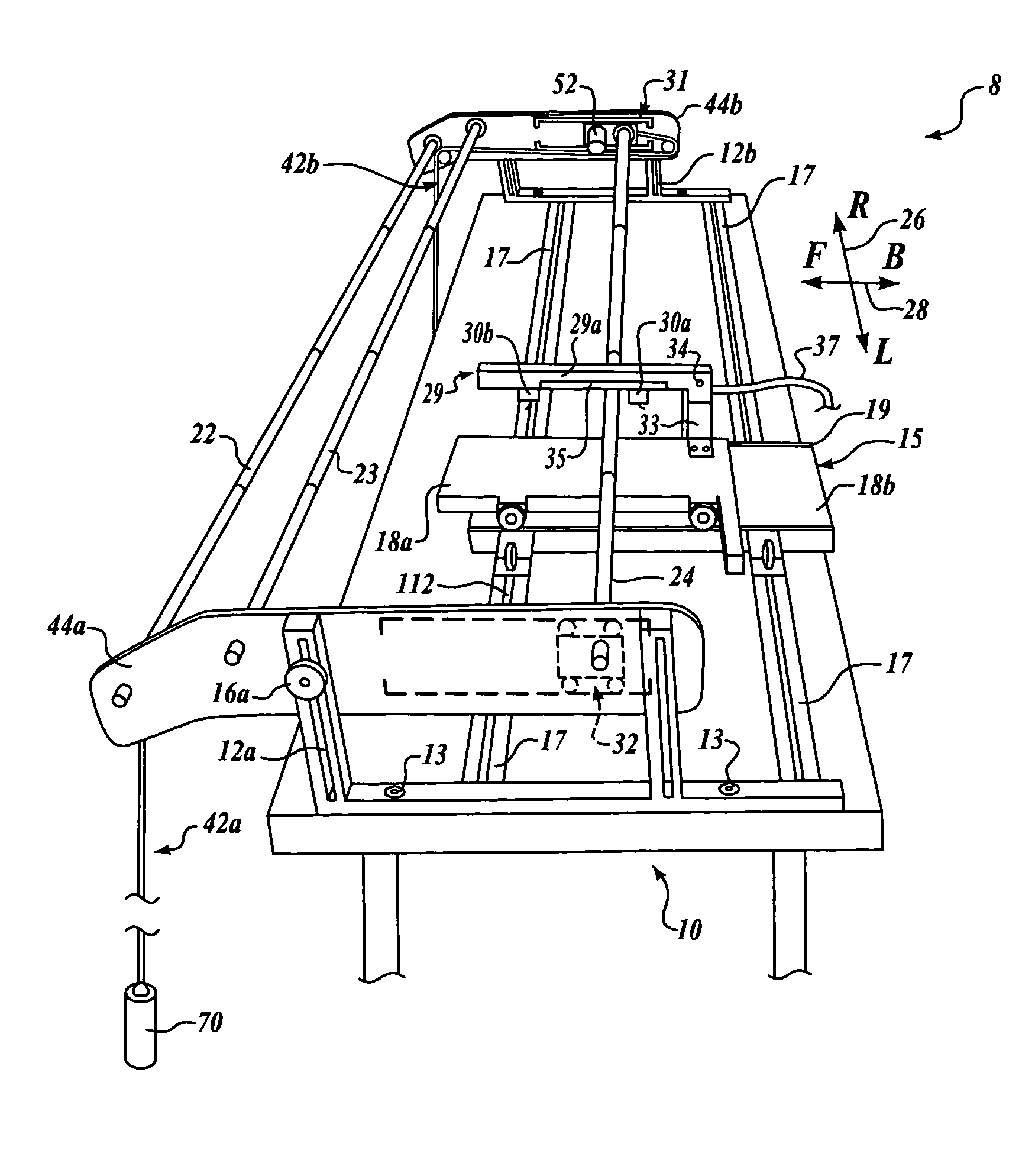
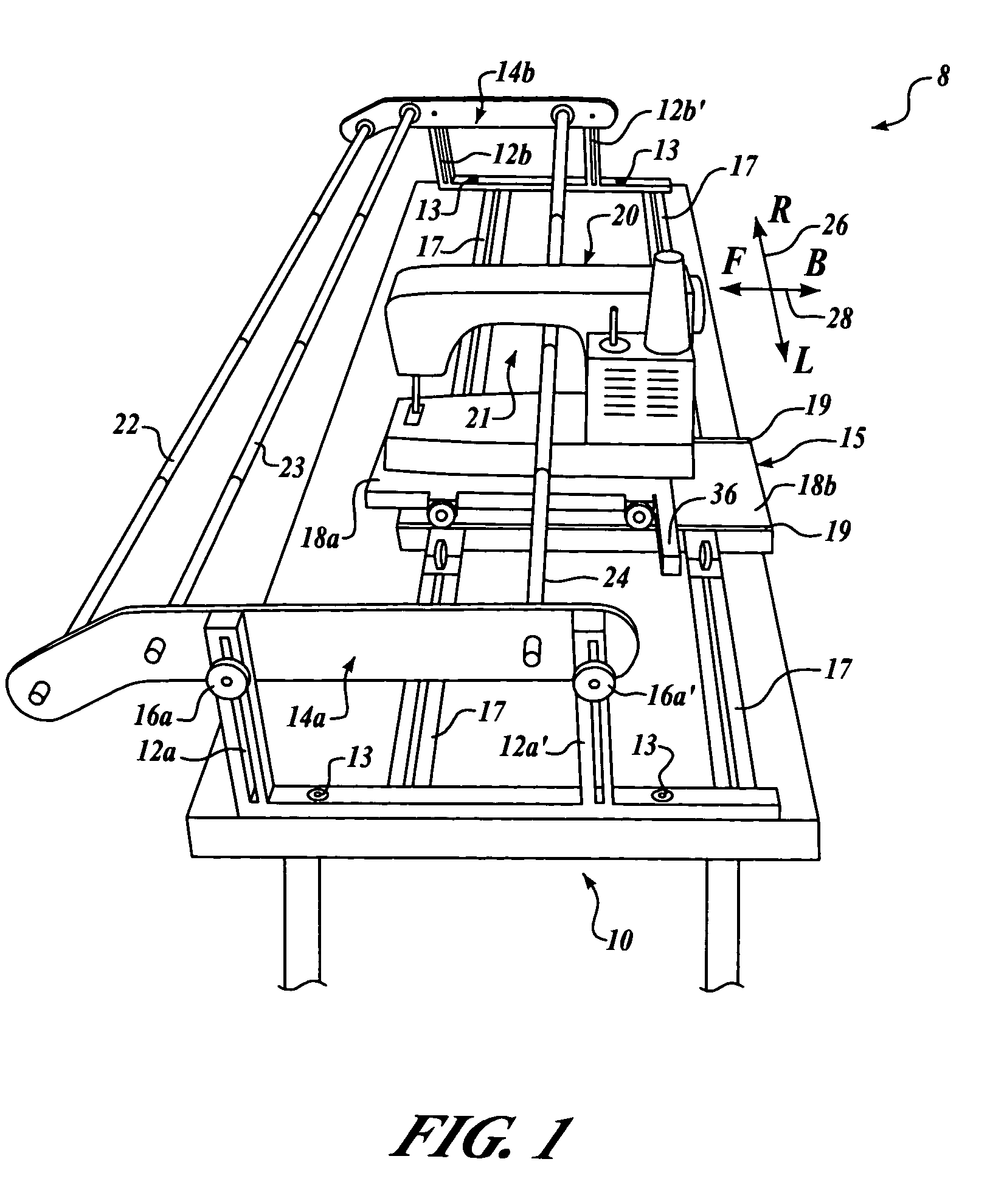
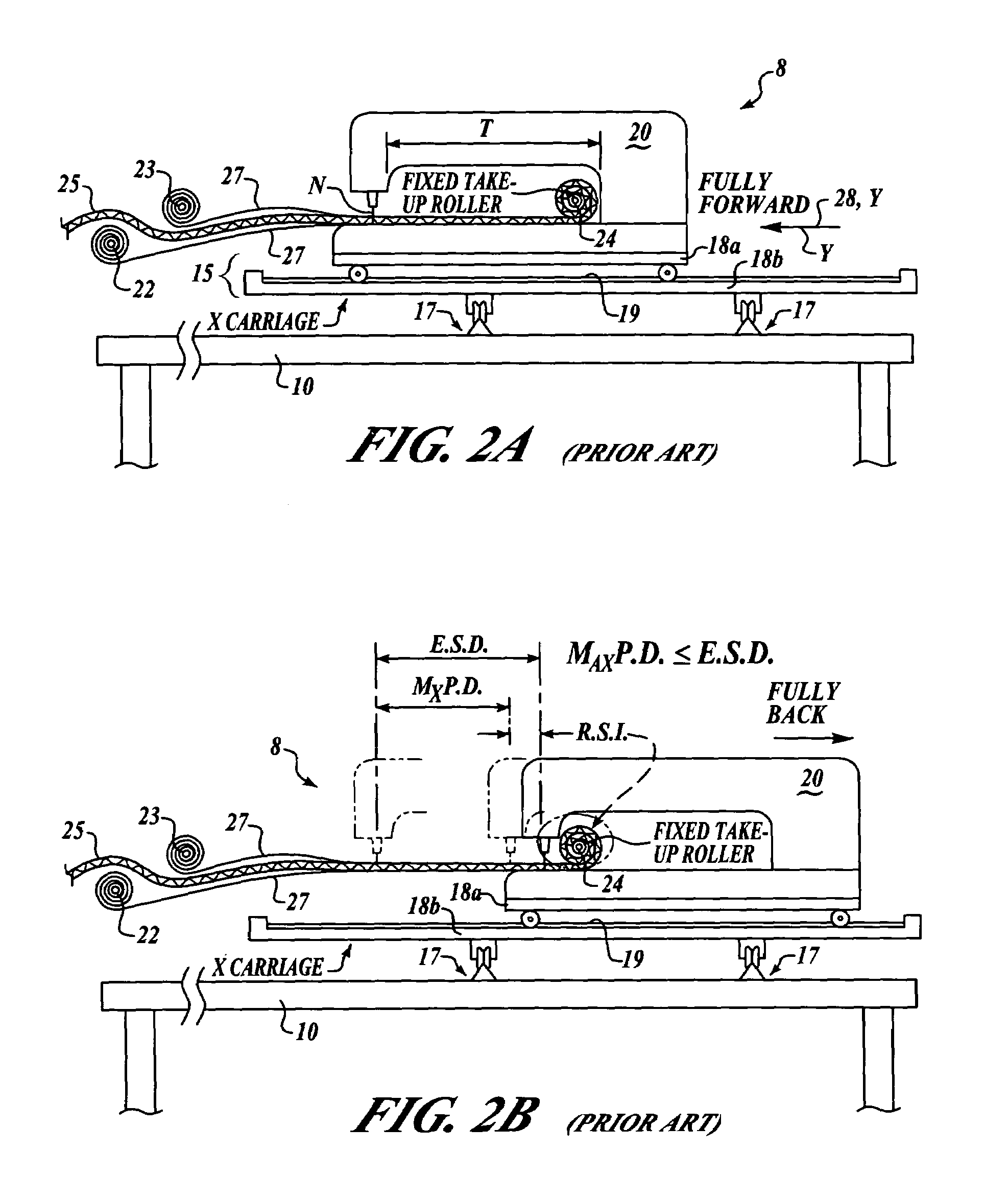
[0054]In this regard, the invention is illustrated in the several figures, and is of sufficient complexity that the many parts, interrelationships, and sub-combinations thereof simply cannot be fully illustrated in a single patent-type drawing. For clarity and conciseness, several of the drawings show in schematic, or omit, parts that are not essential in that drawing to a description of a particular feature, aspect or principle of the invention being disclosed. Thus, the best mode embodiment of one feature may be shown in one drawing, and the...


PUM


Abstract

An improved quilting apparatus and method for automatically providing a variable sewing area (VSA) independent of the throat depth of the sewing machine used and X / Y carriages on which the sewing machine is mounted, comprising a rotatably-powered take-up roller mounted on laterally movable carriages, a tension system for continuous tension on fabric and batting, arm-mounted or sewing machine-mounted sensors that detect proximity or engage fabric on the take-up roller and cause rotation of the take-up roller so that it is out of the way of the advancing or returning sewing machine. The inventive VSA system includes a microprocessor-based controller for automatic operation, which controller interfaces with PC operated quilting programs that drive powered X / Y carriage systems to allow sewing of quilting patterns much larger than the throat depth of conventional sewing machines.

Description

CROSS REFERENCE TO RELATED APPLICATIONS[0001]This application is the Regular U.S. Application of prior Provisional Application Ser. No. 60 / 497,812 filed Aug. 25, 2003 under the same title by the same inventor, the filing date of which is claimed for priority under 35 U.S. Code § 120.FIELD[0002]This invention relates to quilting devices, and more particularly, to apparatus and methods for quilting and sewing patterns of a larger size than would otherwise be possible using a commercially available consumer sewing machine with a limited throat depth in association with a conventional quilting frame, characterized by a moveable, powered take-up roller maintained under constant tension and controlled by a sensor system to provide a movable work area that permits sewing quilting patterns laterally larger than the throat depth of the sewing machine used.BACKGROUND[0003]Quilting has been practiced for several centuries throughout the world. Quilts were originally used as bed covers for warm...

Claims


Application Information

Patent Timeline
Patent Type & Authority Patents(United States)
IPC IPC(8): D05B11/00D05B21/00
CPCD05B11/00
Inventor CANAN, TIMOTHY G.
Owner MCMUFFIN & SNUFFLES
Why Eureka
Try Eureka