Apparatus for sawing a workpiece

a technology for workpieces and apparatuses, applied in the field of apparatus for sawing workpieces, can solve the problems of cants being moved laterally toward the opposite anvil, cants deflecting laterally away, and excessive amount of chipping, so as to improve stability, reduce the lateral unsupported distance on cants, and reduce the processing time.

Inactive Publication Date: 2006-01-31
USNRKOCKUMS CANCAR
View PDF17 Cites 8 Cited by
  • Summary
  • Abstract
  • Description
  • Claims
  • Application Information

AI Technical Summary

Benefits of technology

[0005]In one embodiment, the present invention includes a pair of independently laterally actuable chipping heads upstream of a pair of associated combination anvils / chip chutes (or deflectors) hereafter collectively referred to as anvils and live press rolls positioned on each side of a cant. The chipping heads open opposite faces of the cant. The anvils and press rolls guide the cant toward and through the gang saw. The anvils and press roll are positioned adjacent to saws and immediately downstream from the chipping heads. The pair of anvils and the pair of press rolls on each side of the cant are independently movable by actuation of a linear positioner toward or away from the sides of the cant and are independently movable with respect to the associated chipping head. The linear positioner may translate them linearly laterally or pivot them about the axes of rotation of the chipping heads. The chipping heads anvils and press rolls follow a path according to an optimized cut path determined by an optimizer. The press rolls are brought into firm contact with the sides of the cant as the cant travels toward the saws so as to resist asymmetrical chipping forces on the cant, which tend to deflect the cant from the optimized cutting solution. Since the press rolls are live and positioned adjacent to the saws, the trailing end of the cant is better stabilized and the lateral unsupported distance on the cant is markedly reduced thereby allowing shorter cants to be processed.

Problems solved by technology

Due to the fixed positioning of the anvils, the chipping head can not be positioned into the cant which results in excessive amounts of chipping when cants are fed butt first or for example when they have flares or bulges along their length.
However, when asymmetric chipping loading occurs on one side of cant, for example when the chipping knives impact a side of the cant where more chipping is required, this loading results in the cant being moved laterally toward the opposite anvil.
Asymmetric chipping loads may cause the cant to deflect laterally away from the optimizer's optimized board recovery solution.

Method used


Image

  • Apparatus for sawing a workpiece
  • Apparatus for sawing a workpiece
  • Apparatus for sawing a workpiece

Examples


Embodiment Construction

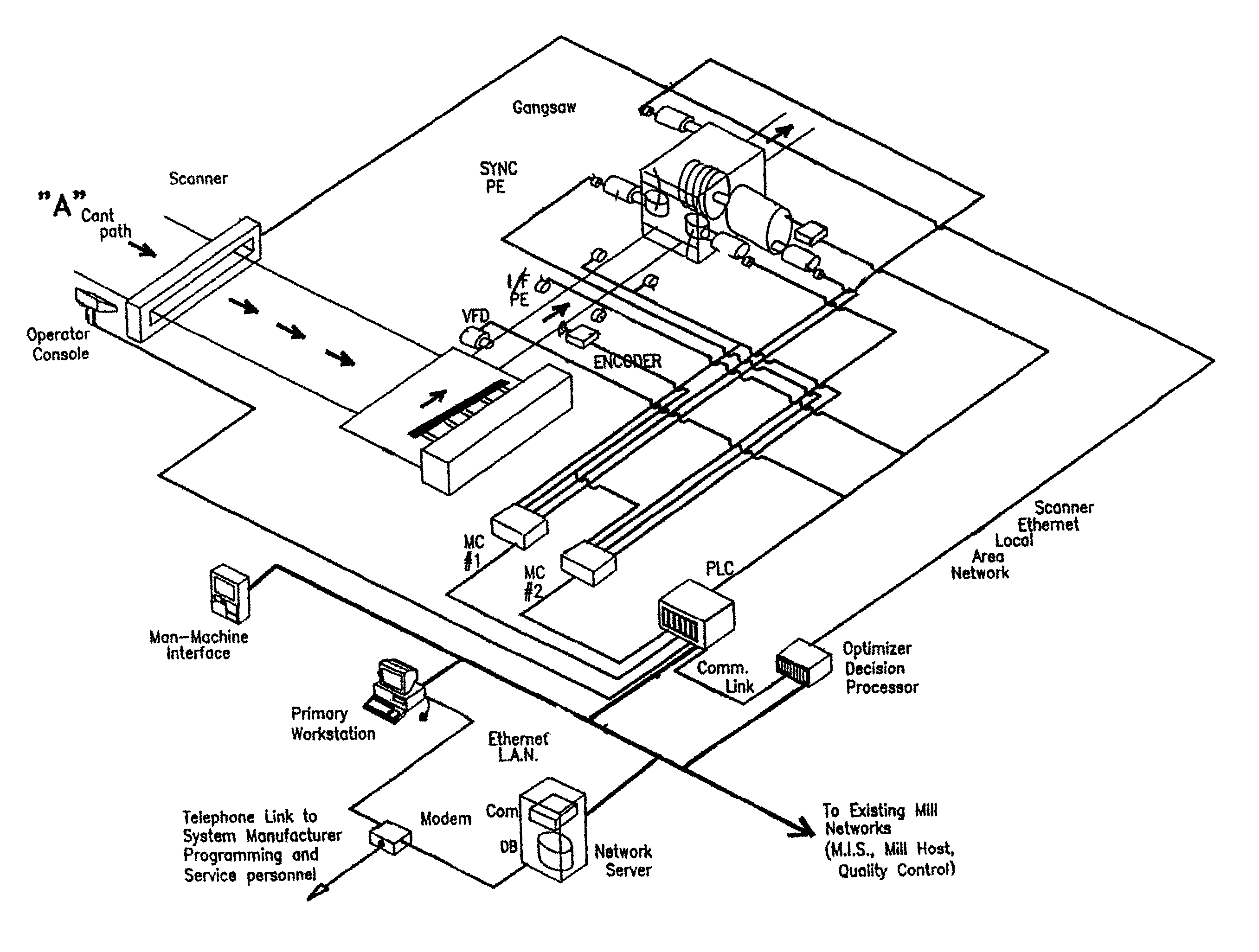
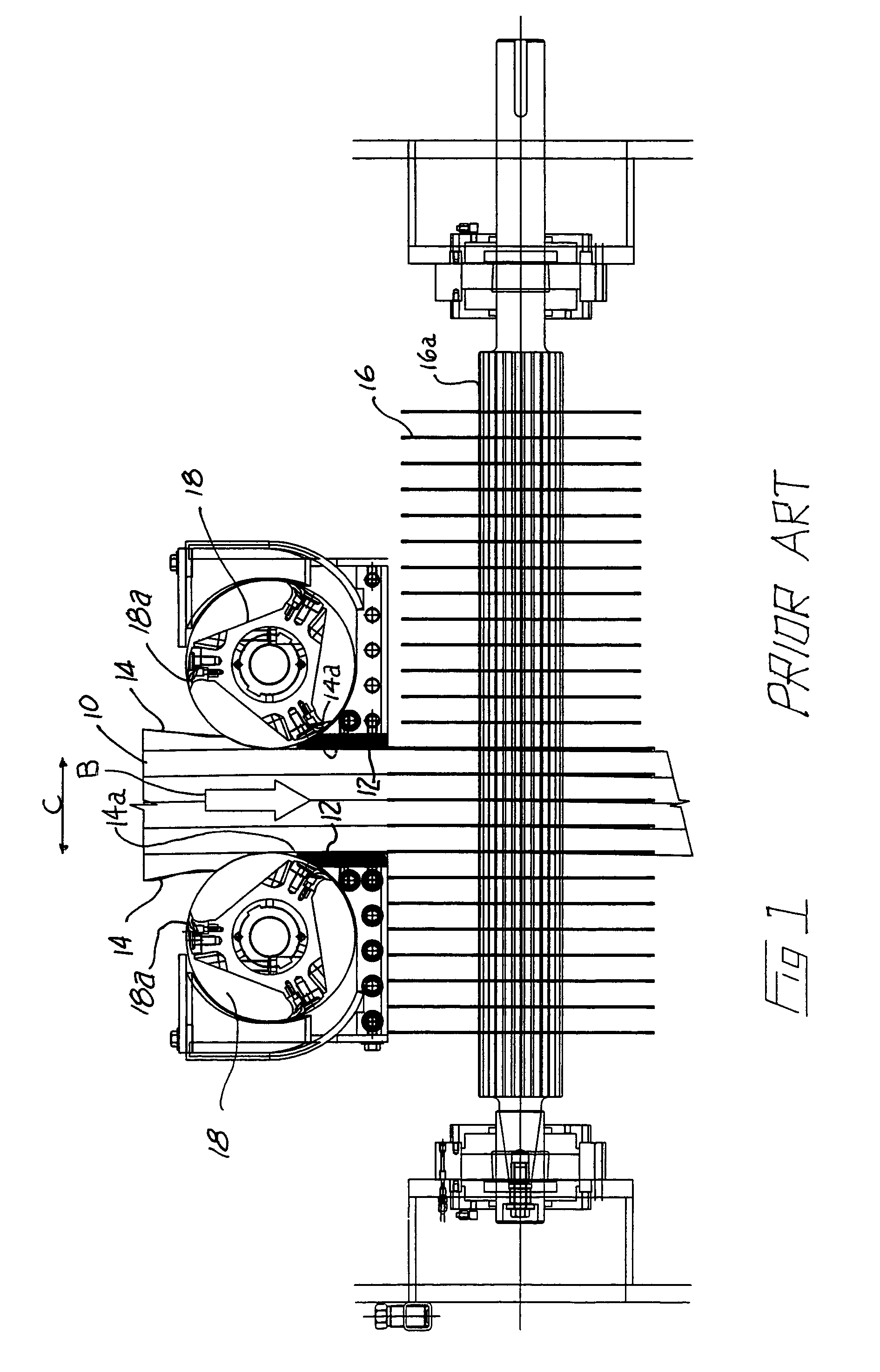
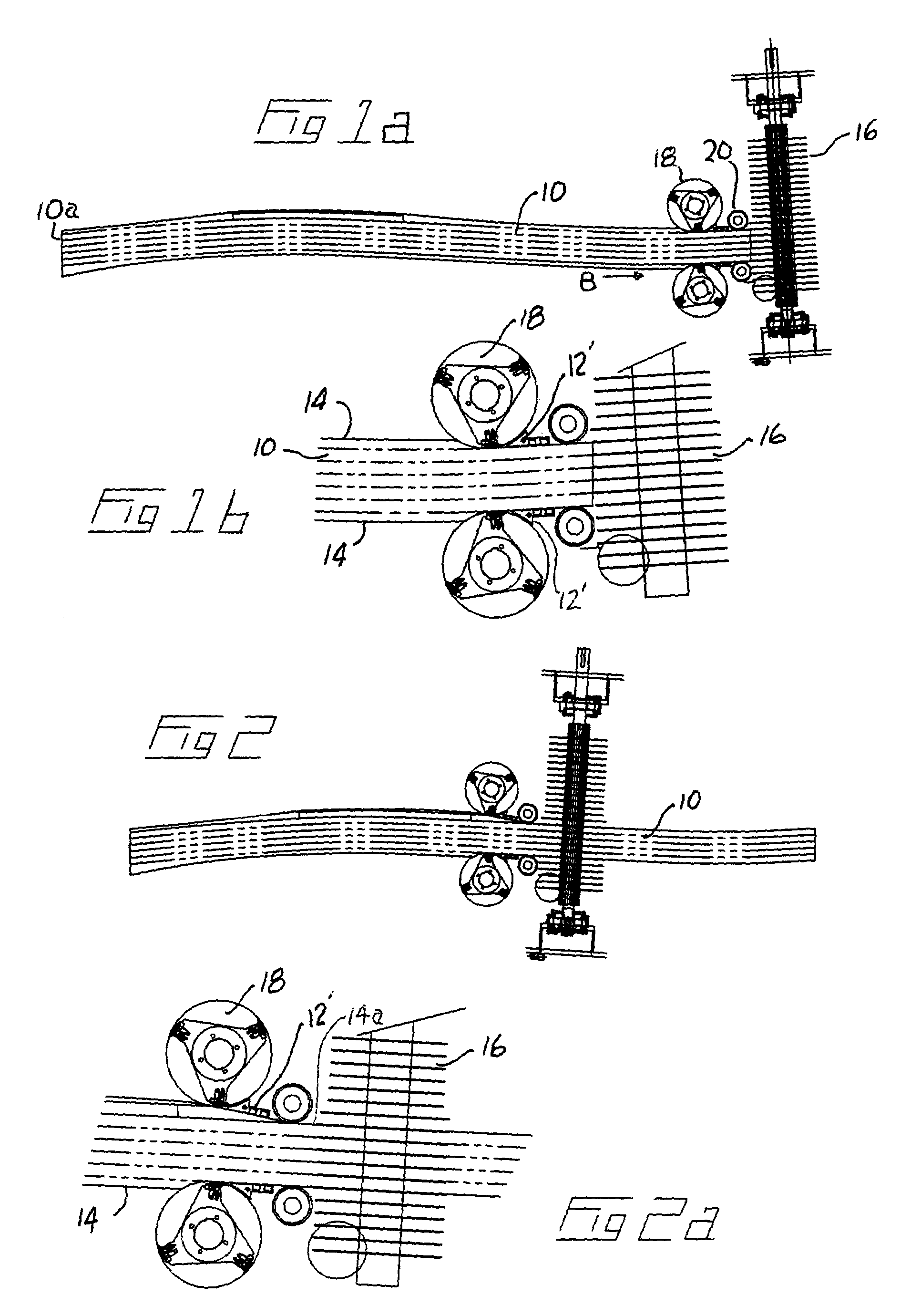
[0027]With reference to the drawing figures, wherein similar characters of reference denote corresponding parts in each view, as seen in FIG. 1, in the prior art a curved cant 10 was fed between anvils 12 located adjacent the sides 14 of the cant, for accurate infeed to arbor-mounted saws 16 mounted on splined arbor 16a. Anvils 12 may be mounted intermediate of, or between upstream chipping heads 18 and downstream saws 16. In a curve sawing application, saws 16 in gangsaw 17 are selectively positioned relative to the cant 10 by slewing (lateral translation) and skewing (pivoting relative to the infeed direction) of the arbor or arbor supporting frame 30 or carriage according to instructions from an optimizer for optimized recovery of boards from cant 10. Such curve sawing is described in our previous patent applications, particulars of which are provided above, from which this application claims priority, all of which prior patent applications being incorporated herein by reference....


PUM

PropertyMeasurementUnit
dimensionsaaaaaaaaaa
diameteraaaaaaaaaa
chipping forcesaaaaaaaaaa

Abstract

A method of forming a workpiece into sectioned parts using a pair of laterally translatable chipping heads and, downstream, a cutting device of the type having a plurality of rotatable cutting members mounted for rotation on a common axis which is movable and including workpiece transport means for moving the workpiece from a starting position to a final position along a path which extends first past the chipping heads and then past the cutting device.

Description

CROSS REFERENCE TO RELATED APPLICATIONS[0001]This application claims priority from U.S. Provisional Patent Application No. 60 / 398,133 filed Jul. 25, 2002 entitled Curved Sawing Gang and is a Continuation-In-Part of U.S. patent application Ser. No. 10 / 342,400 filed Jan. 15, 2003 which is a Continuation of U.S. patent application Ser. No. 09 / 505,255 filed Feb. 15, 2000, now U.S. Pat. No. 6,520,228 which is a Continuation of U.S. patent application Ser. No. 09 / 211,047 filed Dec. 15, 1998, now U.S. Pat. No. 6,039,098 which is a Division of U.S. patent application Ser. No. 08 / 822,947 filed Mar. 21, 1997 now U.S. Pat. No. 5,884,682 which claims priority from U.S. Provisional Patent Application No. 60 / 013,803 filed Mar. 21, 1996, U.S. Provisional Patent Application No. 60 / 015,825 filed Apr. 17, 1996 and U.S. Provisional Patent Application No. 60 / 025,086 filed Aug. 30, 1996 entitled Position-Based Integrated Motion Controlled Curve Sawing.FIELD OF THE INVENTION[0002]This invention relates t...

Claims


Application Information

Patent Timeline
Patent Type & Authority Patents(United States)
IPC IPC(8): B23Q15/02B23Q15/08B23Q15/24B23Q15/26B27B1/00
CPCB27B1/007Y10T83/155Y10T83/531Y10T83/538
Inventor MITCHELL, RORY MATTHEWSTROUD, BRIAN
Owner USNRKOCKUMS CANCAR
Why Eureka
Try Eureka