Multiple plane scanning system for data reading applications
What is Al technical title?
Al technical title is built by PatSnap Al team. It summarizes the technical point description of the patent document.
a scanning system and data reading technology, applied in the field of optical scanning systems, can solve the problems of lateral opposite sides, difficulty in scanning faces oriented in a horizontal plane, and limited plane orientation range of objects bearing bar codes
Inactive Publication Date: 2006-01-31
DATALOGIC SCANNING
View PDF76 Cites 184 Cited by
Summary
Abstract
Description
Claims
Application Information
AI Technical Summary
This helps you quickly interpret patents by identifying the three key elements:
Problems solved by technology
Method used
Benefits of technology
Problems solved by technology
The range of suitable plane orientation of the object bearing the bar code is limited by the size of the window and the angle over which the mirror array can direct a scan pattern.
Present vertical scanners can scan bar codes oriented on certain lateral sides (i.e. side facing) which face the vertical window, but experience difficulties in scanning faces oriented in a horizontal plane (i.e., facing up or down) or lateral sides opposite the window.
Horizontal scanners (i.e. upward facing) are fairly adept at scanning the bottom side but are frequently limited as to which lateral sides may be scanned.
Method used
Image
Click on the blue label to locate the original text in one second.
Reading with bidirectional positioning of images and text.
Examples
Embodiment Construction
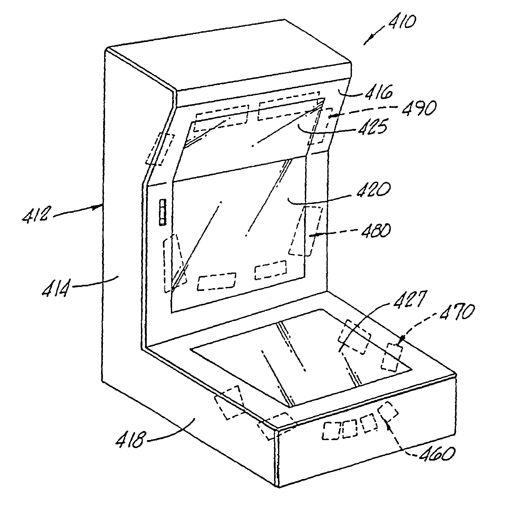
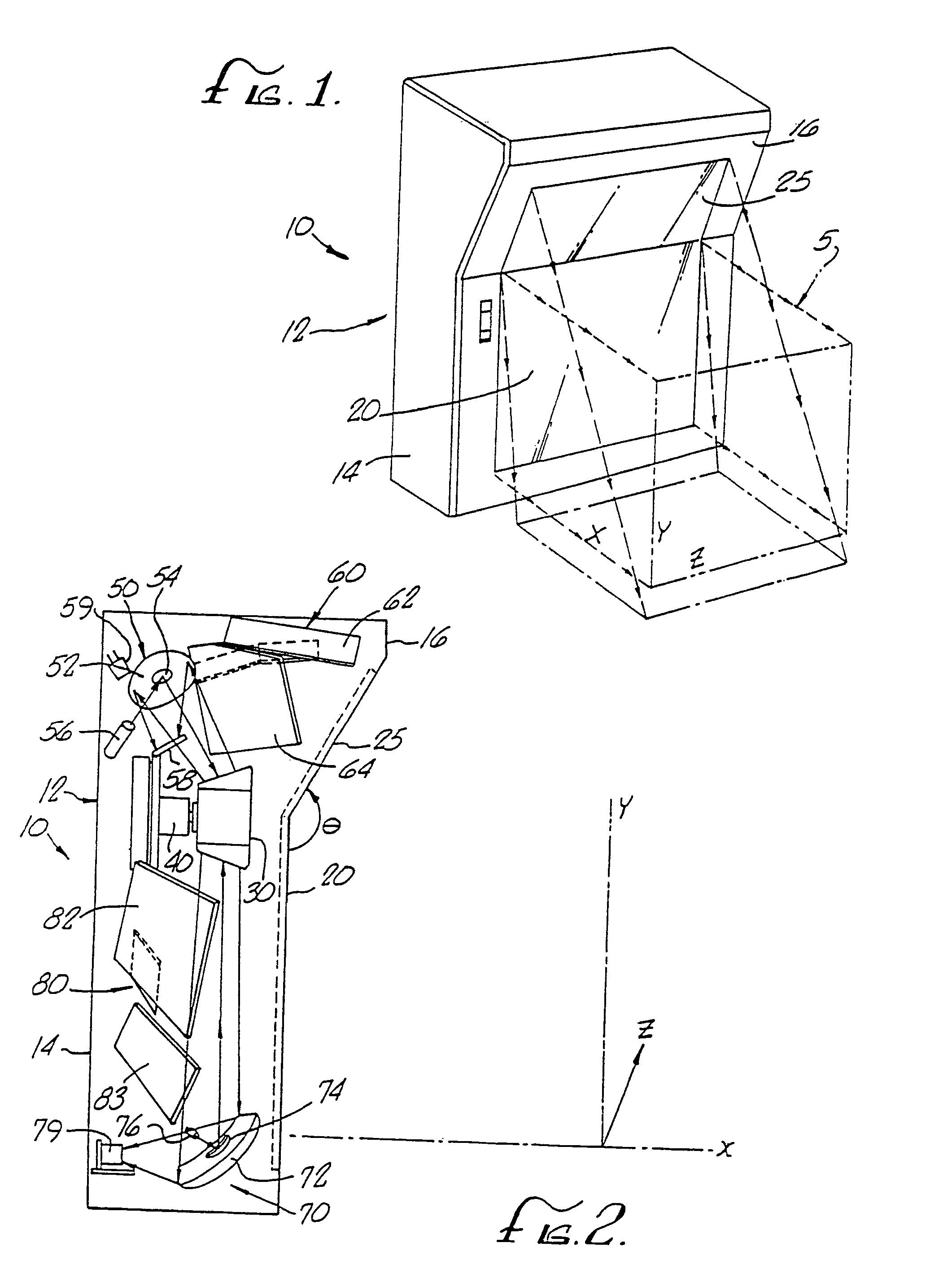
[0037]The preferred embodiments will now be described with reference to the drawings. FIG. 1 is a schematic diagram of a preferred vertical scanner 10 having a housing 12 with a lower housing portion 14 and an upper housing portion 16.
[0038]The scanner 10 generates a scan volume generally designated 5 by scanning beams projected outwardly through lower and upper windows 20 and 25. In order to facilitate referral to relative directions, orthogonal coordinates (X, Y, Z) are designated in FIG. 1. The X coordinate is defined as a sideways direction, perpendicular to or horizontally outward from the lower window 20 of the scanner housing 12; the Y coordinate is defined as a vertically upward direction; and the Z coordinate is defined as another horizontal direction parallel to the lower window 20.
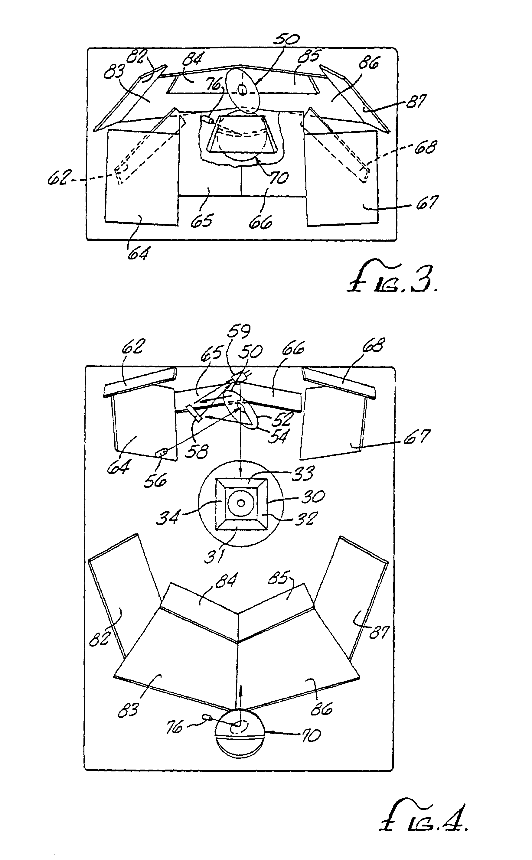
[0039]FIGS. 2–4 illustrate the internal scanning beam generation and collection configuration of the scanner 10. The scanner 10 has two windows namely a lower window 20 and an upper window 25 ar...
PUM
Abstract
An optical system and method for data reading. The preferred system is directed to a scanner which includes a laser diode and a beam splitter for generating first optical beam and a second optical beam, the first optical beam being directed toward one side of a scanning optical element such as a rotating polygon mirror and to a first mirror array, the second optical beam is being simultaneously directed toward a second optical element such as another side of the rotating polygon mirror and then to a second and a third mirror array. The first mirror array is configured to generate a scan pattern through a vertical window and the second and third mirror arrays are configured to generate scan patterns passing through a horizontal window. In combination, the three mirror arrays generate three sets of scan lines so as to scan the bottom and all lateral sides of an object being passed through the scan volume.
Description
RELATED APPLICATION DATA[0001]This application is a continuation of application Ser. No. 10 / 431,070, filed May 6, 2003, which is a continuation of application Ser. No. 09 / 078,196, filed May 13, 1998, now U.S. Pat. No. 6,568,598, which is a divisional of application Ser. No. 08 / 806,194, filed Feb. 26, 1997, now U.S. Pat. No. 5,837,988, which is a divisional of application Ser. No. 08 / 554,819, filed Nov. 7, 1995, now U.S. Pat. No. 5,705,802, which is a divisional of application Ser. No. 08 / 155,112, filed Nov. 19, 1993, now U.S. Pat. No. 5,475,207, which is a continuation-in-part of application Ser. No. 07 / 913,580, filed Jul. 14, 1992, now abandoned.BACKGROUND OF THE INVENTION[0002]The field of the present invention relates to optical scanning systems and particularly to a scanning system capable of successfully reading objects aligned in a variety of orientations. Certain preferred embodiments of the invention are especially suitable for use as a fixed scanner such as that employed at...
Claims
Application Information
Patent Timeline
Application Date:The date an application was filed.
Publication Date:The date a patent or application was officially published.
First Publication Date:The earliest publication date of a patent with the same application number.
Issue Date:Publication date of the patent grant document.
PCT Entry Date:The Entry date of PCT National Phase.
Estimated Expiry Date:The statutory expiry date of a patent right according to the Patent Law, and it is the longest term of protection that the patent right can achieve without the termination of the patent right due to other reasons(Term extension factor has been taken into account ).
Invalid Date:Actual expiry date is based on effective date or publication date of legal transaction data of invalid patent.