
Webbed flange for a reel

a technology of flanges and reels, applied in the field of reels, can solve the problems of damage to reels, bending and/or warping of gripped flanges, and general inapplicability of all-paper reels to certain medium to heavy duty applications, and achieve the effects of preventing damage to the end, reducing the thickness of flange materials, and increasing the structural strength of flanges

Active Publication Date: 2006-01-31
VANDOR CORP
View PDF7 Cites 45 Cited by
  • Summary
  • Abstract
  • Description
  • Claims
  • Application Information

AI Technical Summary

Benefits of technology

[0016]An advantage of the present invention is that, because the flange includes support ridges on both of its sides, bending and warping of the flange is inhibited regardless of which of the two opposite axial directions a force is exerted on the flange. Yet another advantage is that the flange includes concentric walls defining a groove that supports and prevents damage to an end of the core that is received in the groove.
[0017]Still another advantage is that more structural strength of the flange can be achieved with less flange material than with prior flange designs. A more specific advantage is that he wall or web thickness of the flange material can be significantly reduced from prior flange designs. This reduction in thickness reduces material costs without sacrificing strength. A further advantage is that the inventive flange is easier to manufacture by standard injection molding processes, while minimizing hot spots or discontinuities in the molded material.
[0018]A further advantage of the present invention is that, by virtue of the support ridges and the concentric walls sharing a same position in the axial direction, the overall height of the flange is limited. These advantages, as well as particular benefits of the invention, will become more readily apparent to those of ordinary skill in the art by reference to the following detailed description and accompanying drawings.

Problems solved by technology

While such all-paper reels provide significant economy and light weight, all-paper reels are generally not suitable for certain medium to heavy duty applications because the paper flanges do not have the strength of plastic, wood, or steel flanges.
During use, reels are subject to many extraneous forces which can possibly damage the reels.
On the other hand, if the reel is loaded with a heavy metal wound medium, then the weight of the loaded reel can cause the gripped flange to bend and / or warp when the reel is lifted by the flange.
Of course, with increased wall thicknesses also comes increased material costs and weight, neither of which is desirable.
Another way in which a reel may be damaged is if an extraneous force is exerted on a flange, such as if the reel is dropped.
Such a force exerted on a flange will usually damage the pressed cardboard core.
Particularly subject to damage are the ends of the core that engage the flanges.

Method used


Image

  • Webbed flange for a reel
  • Webbed flange for a reel
  • Webbed flange for a reel

Examples


Embodiment Construction

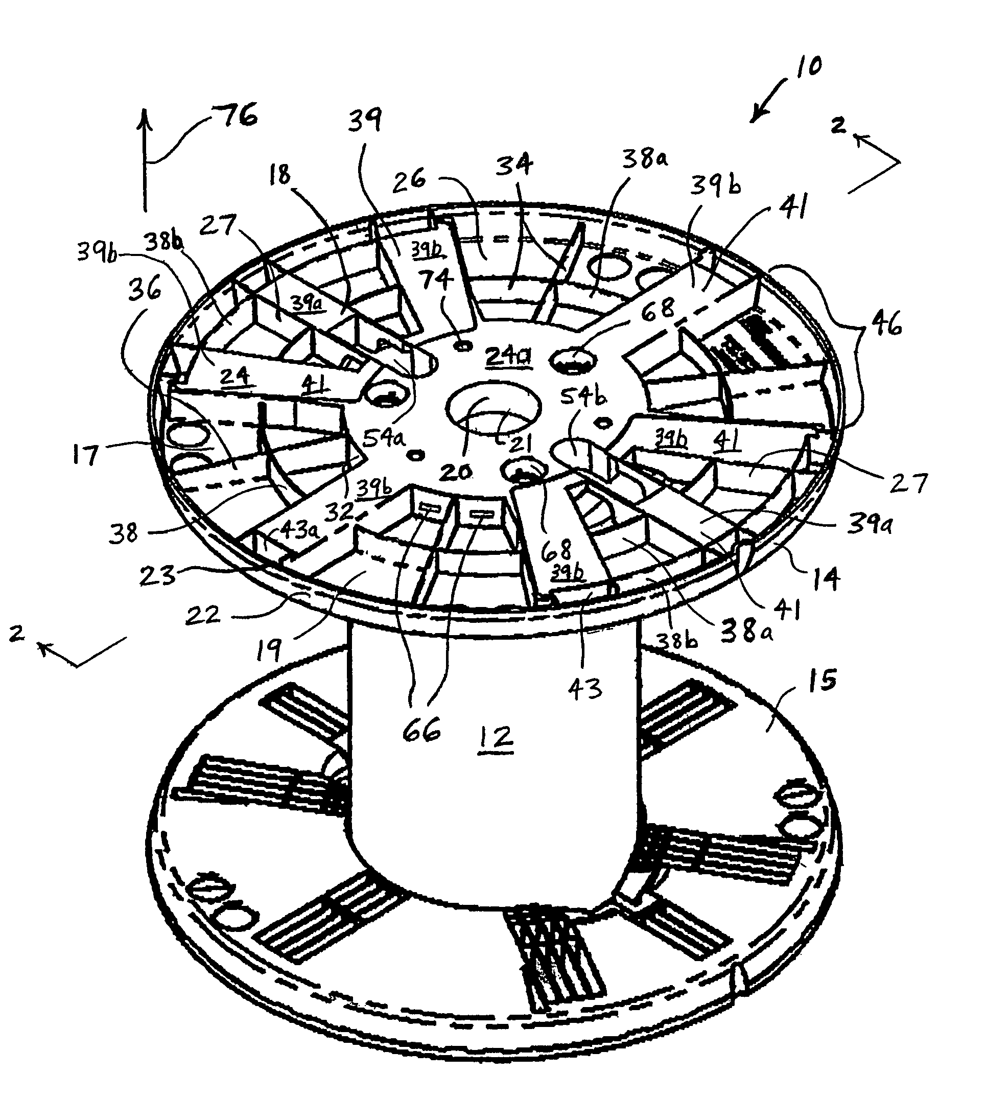
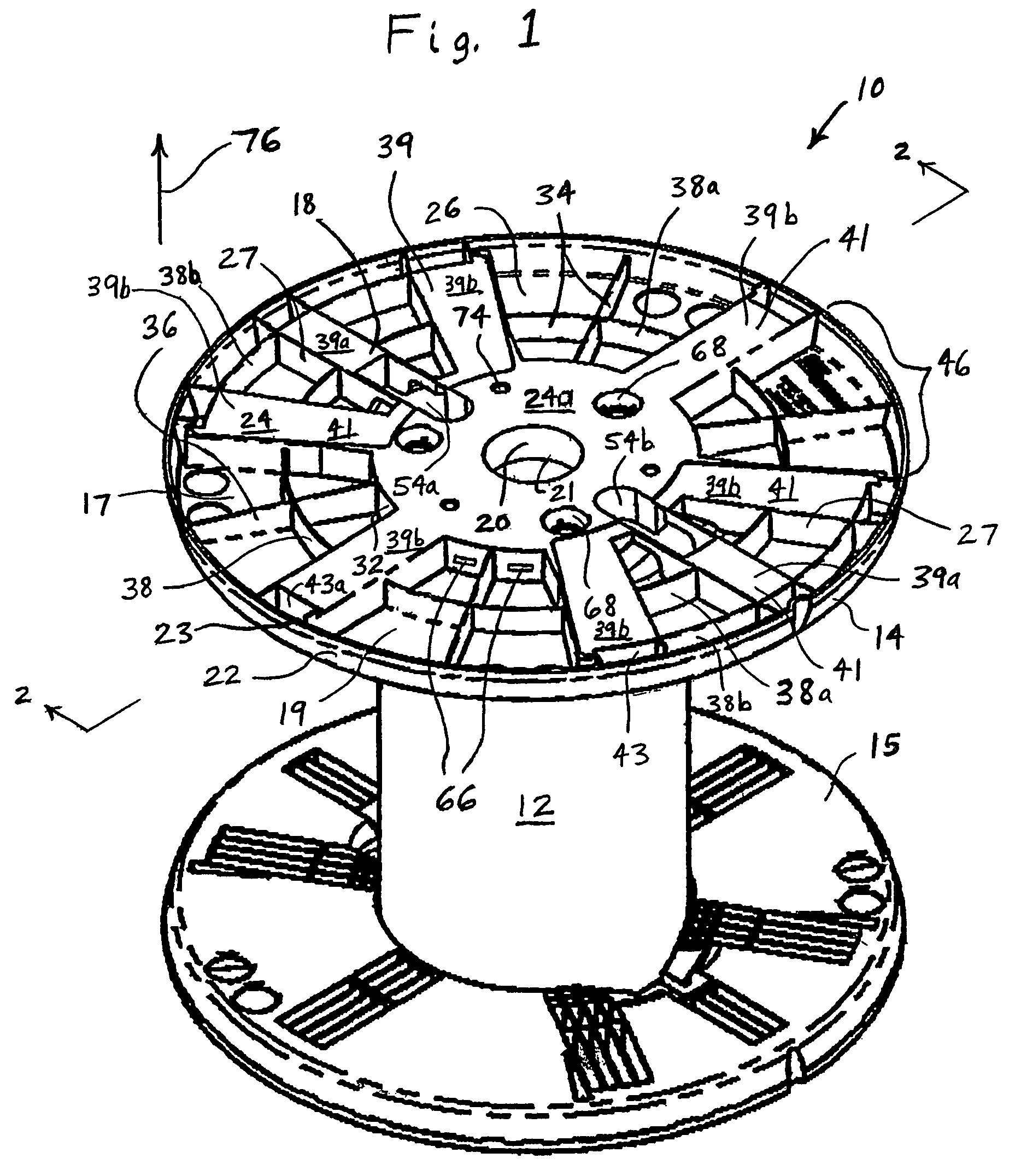
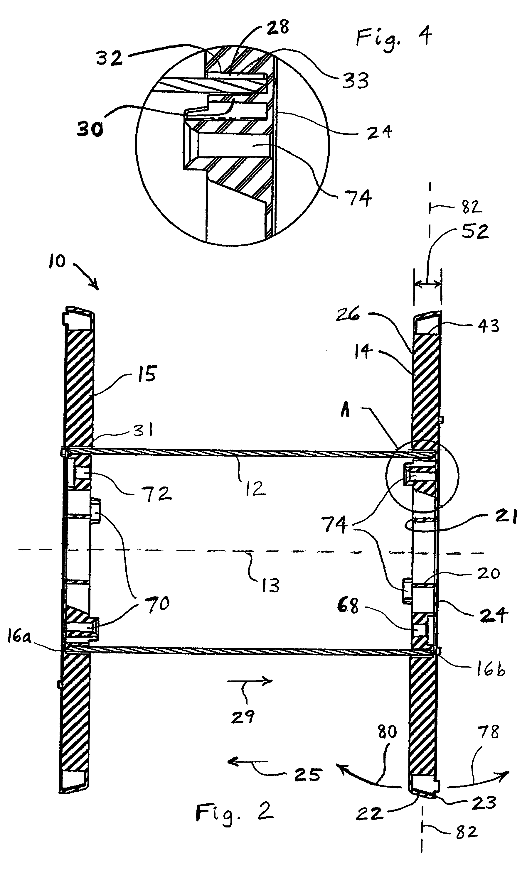
[0023]FIG. 1 shows one embodiment of a reel 10 according to the present invention which includes a core 12, a first flange 14 and a second flange 15. As shown in FIG. 2, the core 12 defines an axis 13 and has two opposite ends 16a, 16b each having a generally circular shape. It is noted that the core 12 typically, but not necessarily, has a substantially uniform shape along its length so the core assumes the configuration of a hollow cylinder. In the exemplary embodiment described herein, the core 12 can comprise a pressed paperboard tube.

[0024]The flanges 14, 15 are preferably molded of a plastic or composite material. However, metal and other rigid materials may be used while still retaining many of the advantages of the present invention.

[0025]The flange 14 comprises an annulus 18 having a plurality of circumferentially-spaced indentations 19 on a radially outer portion of an axially outer side 17 of the annulus 18. The annulus 18 also has an inner annular rim 20 defining an inne...


PUM

PropertyMeasurementUnit
heightsaaaaaaaaaa
heightsaaaaaaaaaa
heightaaaaaaaaaa

Abstract

A flange is for use in a reel for supporting a wound flexible medium. The reel includes an elongated core defining a longitudinal core axis. The flange includes a first annular wall oriented substantially perpendicular to the axis and engaging the core. A second annular wall is oriented substantially perpendicular to the axis and is offset in an axial direction from the first annular wall. At least one connecting wall interconnects the second annular wall and the first annular wall. A first annular rim is attached to the first annular wall or the second annular wall and is oriented substantially parallel to the axis.

Description

FIELD OF THE INVENTION[0001]The present invention relates generally to reels for supporting wound flexible media, and in particular, to reels having a core and at least one flange that is attachable to the core.BACKGROUND OF THE INVENTION[0002]Reels for supporting wound flexible media are employed to both store and facilitate the dispensing of wound media such as rope, wire, chain, and strings of parts. The essential elements of a reel include its core, around which the flexible medium is wound, and its flanges, which prevent the wound flexible medium from migrating axially off of the core. Reels intended for industrial use can vary greatly in size.[0003]Well-designed reels must combine a high strength-to-weight ratio with low manufacturing cost. One reel design that has gained popularity is a reel in which the core is constructed of a pressed paperboard material and the flanges are constructed of a composite or plastic material. The use of paper and plastic components, in general, ...

Claims


Application Information

Patent Timeline
Patent Type & Authority Patents(United States)
IPC IPC(8): B65H75/14B65H75/18
CPCB65H75/14B65H2701/51524B65H2701/5124B65H2701/5122
Inventor COX, GARY L.DAVIS, GERALD H.EVERSOLE, CHAD L.
Owner VANDOR CORP
Learn More