Continuously variable transmission apparatus

a transmission apparatus and continuously variable technology, applied in the direction of friction gearings, gearing elements, gearings, etc., can solve the problems of affecting the operation of the vehicle, affecting the safety of the driver, and requiring a large effort to stop the vehicl

Inactive Publication Date: 2006-01-31
NSK LTD
View PDF7 Cites 120 Cited by
  • Summary
  • Abstract
  • Description
  • Claims
  • Application Information

AI Technical Summary

Benefits of technology

[0060]With the continuously variable transmission apparatus that is constructed as has been described above, even if relatively inexpensive rotation sensors are used, the rotational speed and direction of the output shaft which is rotating at low speeds or is in a stationary state can be identified. Namely, the rotational speed and direction of the output shaft can be obtained from the rotational speeds of the input and the output side disks of the toroidal-type continuously variable transmission unit and the gear ratio (the ratio of numbers of teeth) of the differential unit through calculation. In addition, the input and output side disks rotate at far faster speeds than the output shaft even in the state in which the output shaft rotates at low speeds or is stationary. Consequently, even with the relatively inexpensive rotation sensors, the rotational speeds of the input and output side disks can be measured with accuracy, thereby making it possible to identify the rotation speed and rotation direction of the output shaft with accuracy.

Problems solved by technology

Due to this, unless the regulation of the transmission ratio of the toroidal-type continuously variable transmission unit 25 is implemented strictly, the driver possibly feels an abnormal feeling or the proper operation of the vehicle is possibly made difficult.
In this case, unless a strict regulation of the transmission ratio of the toroidal-type continuously variable transmission unit 25 is implemented and, as a result, a large torque is applied to the output shaft 38, a large effort to depress the brake pedal is required to stop the vehicle, whereby the driver is fatigued largely.
In the case of the construction such as described in JP-A-10-3461, however, because the control is implemented based only on the difference in pressure, it is difficult to make the posture of the trunnion stationary at the moment the passing torque has matched a target value.
Specifically speaking, since an amount in which the trunnion is displaced becomes large due to the control of the torque, a so-called overshoot (and, furthermore, a hunting in association with such an overshoot) tends to occur easily in which the trunnion does not stop at the moment the passing torque has matched the target value but continues to be displaced, and hence the control of the passing torque is not stabilized.
Consequently, a permissible range where the speed ratio can be regulated is limited to a range where no unbearable force is applied to the abutment portions, and hence, when compared with the low-speed running case, the permissible range becomes limited.
However, a rotation sensor which can grasp the rotational speed of the output shaft 38, 38a while rotating at extremely low speeds or the stationary state thereof with accuracy increases the costs.
A so-called active-type rotation sensor is known in which magnetism detection elements such as hall elements and magnetic resistance elements are combined with a permanent magnet, but the rotation sensor of the type is expensive.
Further, in a case of that rotational speed is extremely low, it can not be avoided that an response is slow.
However, with the passive-type rotation sensor, in case the rotation speed of a portion to be detected is slow, the voltage of electric current induced in the coil becomes low, and the rotation speed of the relevant portion cannot be detected.
While, with a plurality of rotational sensors being combined together, such a movement can be identified, increases in costs and installation space cannot be avoided.

Method used


Image

  • Continuously variable transmission apparatus
  • Continuously variable transmission apparatus
  • Continuously variable transmission apparatus

Examples


Embodiment Construction

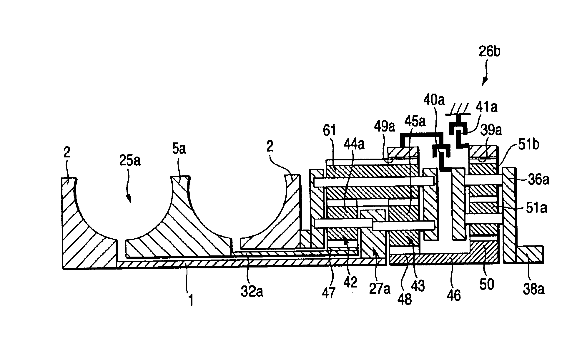
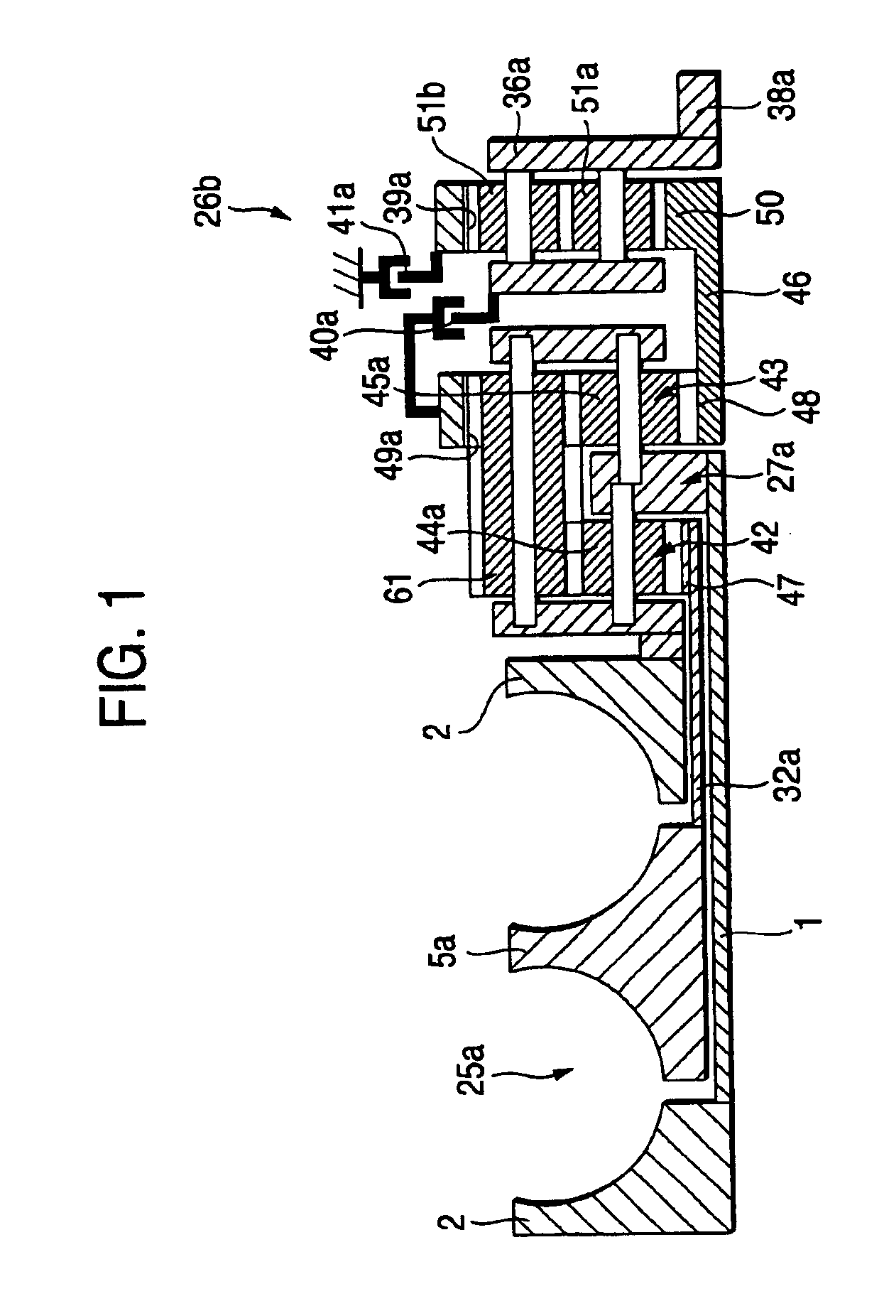
[0073]FIGS. 1 to 3 illustrate an embodiment of the invention. FIG. 1 illustrates an embodiment of a continuously variable transmission apparatus including, in combination, a toroidal-type continuously variable transmission unit 25a and a planet gear-type transmission unit 26b. The construction of this continuously variable transmission system is basically identical with those of the conventional continuously variable transmission apparatus shown in FIG. 7 or the continuously variable transmission apparatus shown in FIG. 8 that has been described above as the improvement over the one shown in FIG. 7. In particular, in the continuously variable transmission apparatus according to the embodiment, of respective planet gear elements which constitute primary and secondary planetary gears 42, 43 of the planet gear-type transmission unit 26b, an axially elongate planet gear element is used as a planet gear element 61 which is provided radially outwardly. Then, this planet gear element 61 is...


PUM


Abstract

A continuously variable transmission apparatus having input and output shafts, a toroidal-type continuously variable transmission unit (CVT unit), a gear-type differential unit with gears, and a control unit, the CVT unit has; input and output side disks, power rollers, input and output side rotation sensors, wherein the differential unit has; a first input portion and a second input portion, and wherein the control unit regulates the transmission ratio of the CVT unit so as to change relative displacement speeds of the gears of the differential unit to thereby convert the rotational state of the output shaft to forward and backward rotations with a stationary state being interposed therebetween, with the input shaft being kept rotating in one direction, and to calculate a rotational speed of the output shaft based on rotational speeds of the input and output side disks and a gear ratio of the differential unit.

Description

BACKGROUND OF THE INVENTION[0001]1. Field of the Invention[0002]The present invention relates to an improvement in a continuously variable transmission apparatus incorporating a toroidal-type continuously variable transmission unit which is used as a vehicle (automotive) automatic transmission apparatus, and more particularly to an improvement in characteristic when a vehicle is stationary or drives at extremely low speeds.[0003]2. Description of Related Art[0004]The usage of a toroidal-type continuously variable transmission unit as shown in FIGS. 4 to 6 as an automotive automatic transmission apparatus has been studied and has now been implemented partially. This toroidal-type continuously variable transmission unit is such as to be called a double-cavity type, in which input side disks 2, 2 are supported around both end portions of an input shaft 1 via ball splines 3, 3. Consequently, these two input side disks 2, 2 are supported coaxially with each other and rotatably in a synch...

Claims


Application Information

Patent Timeline
Patent Type & Authority Patents(United States)
IPC IPC(8): F16H37/02F16H37/08F16H61/00F16H61/662
CPCF16H37/086F16H61/6648F16H2037/0886F16H61/12
Inventor INOUE, EIJI
Owner NSK LTD
Why Eureka
Try Eureka