Artificial heart valve

a heart valve and artificial heart technology, applied in the field of artificial heart valves, can solve the problems of no real satisfactory solutions and catastrophic results of the affected person, and achieve the effects of improving the resistance to wear of materials, low weight, and low wear

Inactive Publication Date: 2006-01-31
SIEVERS HANS HINRICH
View PDF9 Cites 290 Cited by
  • Summary
  • Abstract
  • Description
  • Claims
  • Application Information

AI Technical Summary

Benefits of technology

[0009]The heart valve according to the invention employs principles for the design of the joints between the flap elements and the annular body, which are completely different from those used in the prior art designs. The joint at the annular body, which forms with the joint at the flap element a pivot joint, is intentionally so arranged that the pivot axis for the flap element is moved toward the center of the annular body that is toward the longitudinal center axis of the aorta in order to move the joint as far as possible into the area of the highest flow speed of the blood. As a result, all areas of the respective joint between the flap elements and the annular body are in contact with the fast flowing blood through the center area of the annular body so that no areas of stagnant blood can develop in the joint areas and the formation of blood clots is essentially prevented.
[0029]In order to increase the resistance to wear of the materials, from which the annular body and / or the flap elements are formed, and to increase their biocompatibility, it is advantageous to coat the annular body and / or the flap elements with a hard material layer for example of boron-carbide or a similar layer which may be applied by well-known classic coating processes such as the PVD process (physical vapor deposition) and / or the CVP process (chemical vapor deposition).

Problems solved by technology

However, all artificial heart valves of this type have the disadvantage that the joint area between the annular body and the flap elements negatively affect the flow dynamics of the blood through the opening of the annular body so that zones are formed in the joint areas in which blood is stagnant.
In the areas in which the blood is stagnant in these valves blood clots are formed which are released from time to time and are then transported with the blood flowing through the aorta into remote body parts for example into the brain where they may block the blood passages with catastrophic results for the person affected thereby.
It has been tried with sophisticated designs to reduce to a minimum the areas near the joints where the blood can stagnate in order to minimize the chances of blood clot formation and it has also been tried to arrange the joints or the joint areas in such a way that the areas between the joint and the annular body are flushed by the blood flowing through the annular body so that these areas are kept “clean”, in order to avoid the formation of blood clots but no really satisfactory solutions have been found.

Method used


Image

  • Artificial heart valve
  • Artificial heart valve
  • Artificial heart valve

Examples


Embodiment Construction

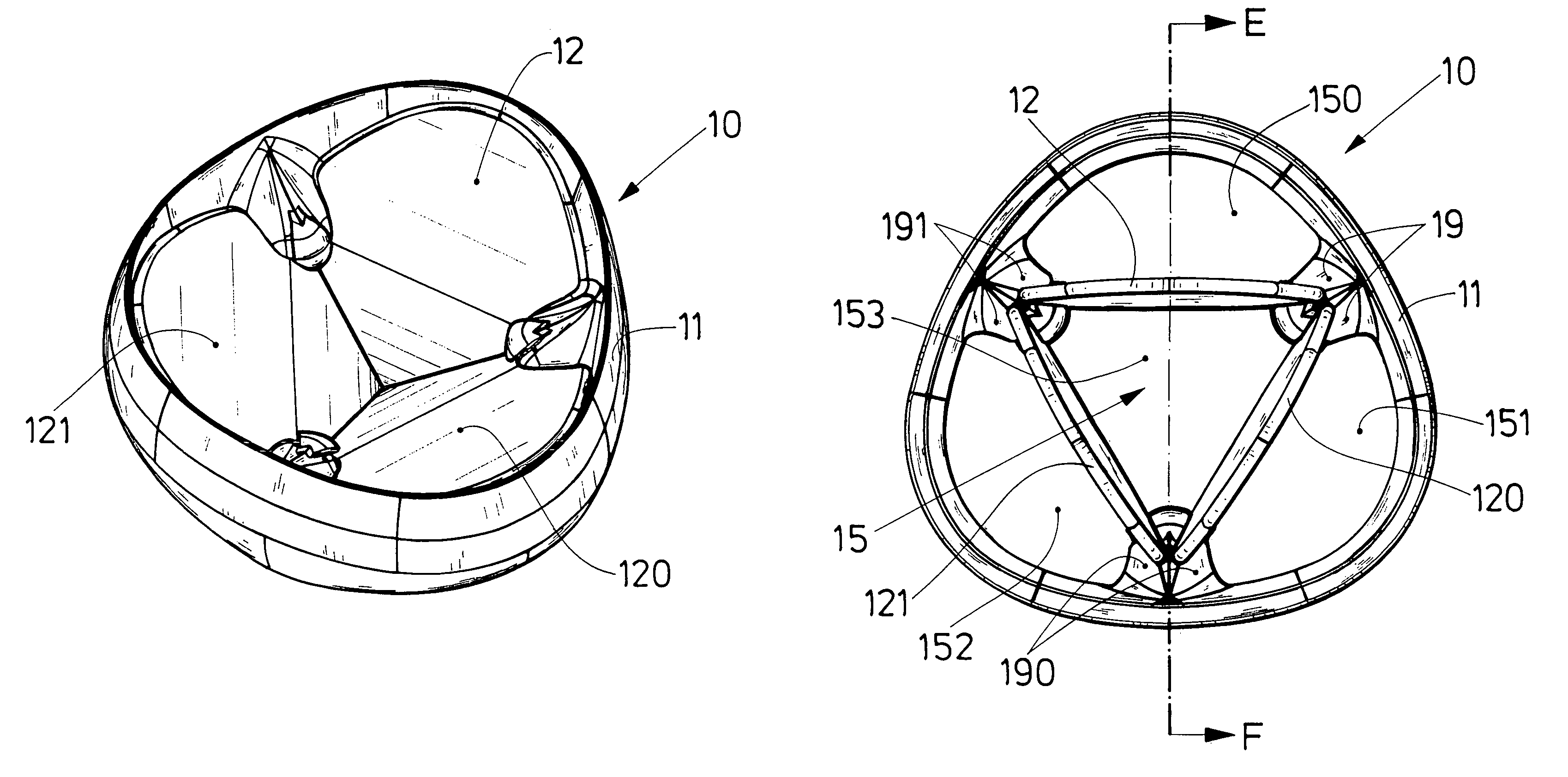
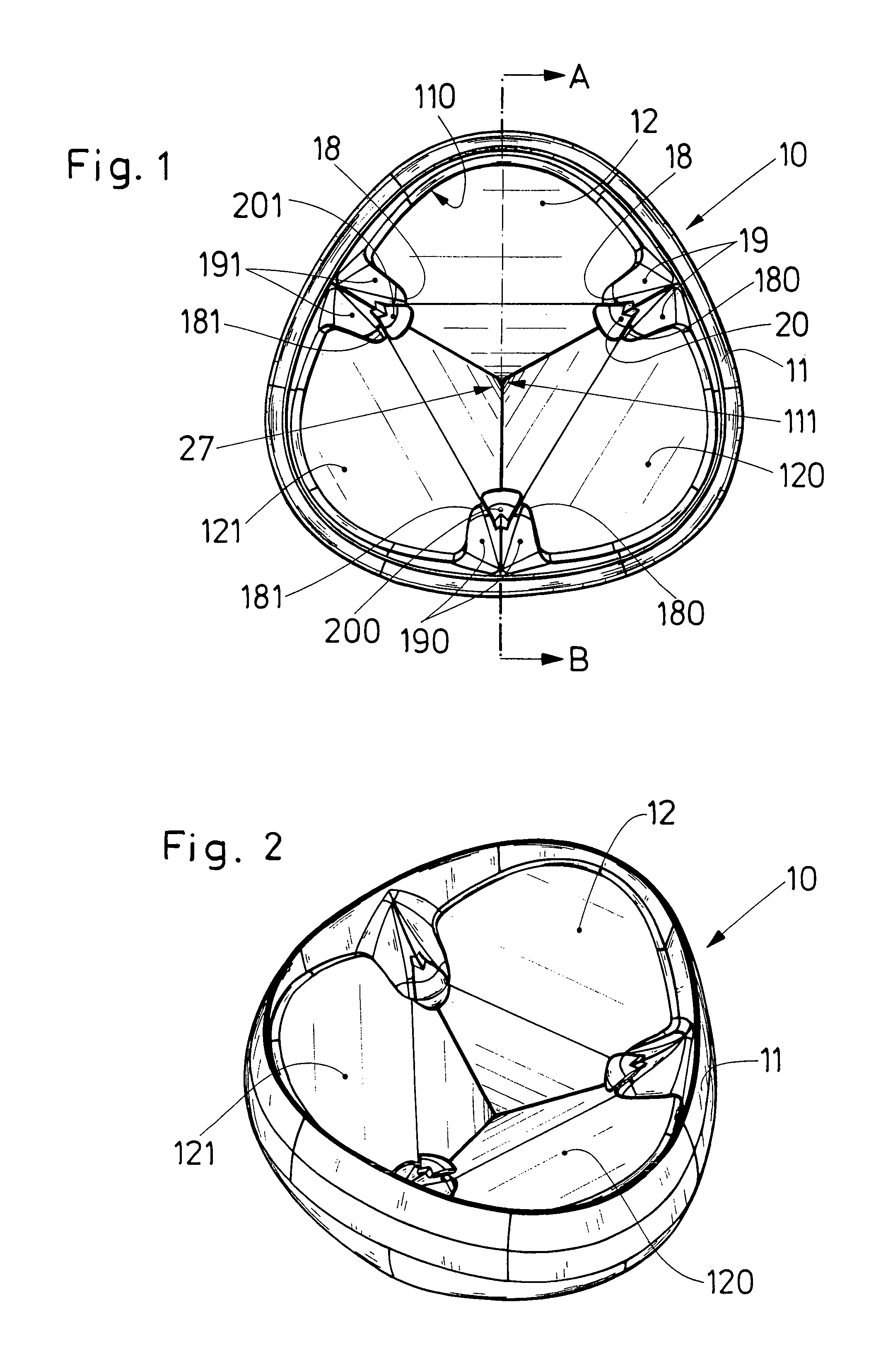
[0048]First reference is made to FIG. 1 where the artificial heart valve 10 is shown in a closed position and to FIG. 7 where the artificial heart valve 10 is shown in an open position. The FIGS. 1 and 7 are top views showing the heart valve 10 from that side, which, after implantation of the heart 14, faces the heart 14.

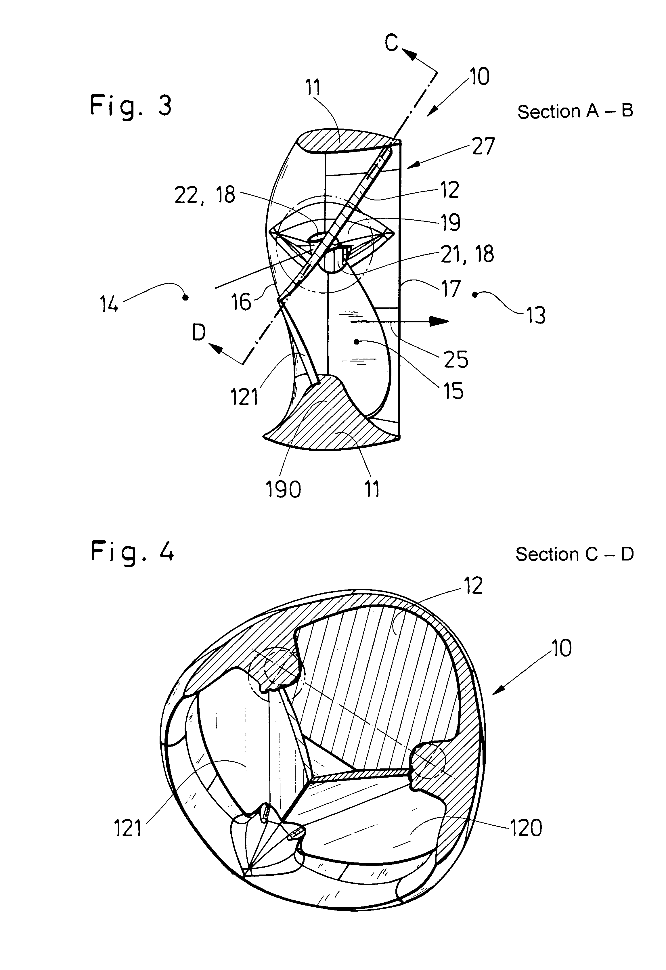
[0049]The artificial heart valve 10 comprises essentially an annular body 11, which has a shape resembling an equal-sided triangle with rounded corners. The annular body 11 however may also be circular or have a cross-section of another form. The artificial heart valve 10, described below as an example, includes three flap elements 12, 120, 121, however, in principle, the inventive concept can be realized also with a valve having only one flap element or two flap elements. Also designs with more than three flap elements 12, 120, 121 are conceivable. The annular body 11, which is insertable into the aorta 13 and the heart 14 in a known manner and which can be fixed t...


PUM


Abstract

In an artificial heart valve for the replacement of an aortic or a mitral valve, including an annular body, which is provided at its outer circumference with means for mounting the artificial valve in place by surgical procedures and which defines in its interior a blood flow passage in which valve flap elements are pivotally supported so as to open or close the blood flow passage depending on their pivot positions, the annular body includes circumferentially spaced projections extending into the flow passage and being provided at their inner ends with pivot joints on which the valve flap elements are pivotally supported.

Description

BACKGROUND OF THE INVENTION[0001]The invention relates to artificial heart valves, that is, to a prosthesis for the replacement of aortic and mitral valves of a heart, comprising an annular body receiving a plurality of pivotal flap elements which annular body can be mounted into the aorta or the mitral valve ring and can be retained therein by surgical procedures so that the flap elements open or close the passage through the valve ring depending on their pivot positions.[0002]A prosthesis, that is an artificial heart valve, of this type is known from WO-A-8504094. For some decades now, heart valve prostheses have been implanted into the aorta leading away from the heart. The first artificial heart valves were ball-type check valves which, with time, were replaced by more sophisticated designs. Heart valves with single flap elements and also with three-flap elements are known. The valve disclosed in WO-A-85 04094, for example, is a three-flap valve. Heart valves with flap elements ...

Claims


Application Information

Patent Timeline
Patent Type & Authority Patents(United States)
IPC IPC(8): A61F2/24
CPCA61F2/2403
Inventor SIEVERS, HANS-HINRICH
Owner SIEVERS HANS HINRICH
Why Eureka
Try Eureka