Liquid droplet ejecting apparatus, electro-optical device, method of manufacturing the electro-optical device, and electronic apparatus

a technology of electrooptical devices and liquid droplets, which is applied in the direction of printing, coating, inking apparatus, etc., can solve the problems of large installation space in plants, and achieve the effects of low manufacturing cost, high accuracy and high accuracy

Active Publication Date: 2006-01-31
KATEEVA
View PDF4 Cites 13 Cited by
  • Summary
  • Abstract
  • Description
  • Claims
  • Application Information

AI Technical Summary

Benefits of technology

[0007]A liquid droplet ejecting apparatus according to the present invention includes: a main body; a work piece mounting unit on which a work piece is mounted; a droplet ejecting head for ejecting liquid droplets of an ejection liquid to the work piece; a relative movement mechanism for relatively moving the work piece mounting unit and the droplet ejecting head; and three or more kinds of droplet ejecting head maintenance units used for function maintenance, function recovery, adjustment, or inspection of the droplet ejecting head, wherein at least three of the droplet ejecting head maintenance units are arranged in a group in a maintenance-unit installing section. As a result, by arranging the plurality of droplet ejecting head maintenance units with high spatial efficiency, it is possible to provide a liquid droplet ejecting apparatus for which the entire space can be effectively utilized. Further, since maintenance by means of various kinds of droplet ejecting head maintenance units in the maintenance-unit installing section can be performed in a group, the cycle time required for one work piece can be shortened, so that it is possible to improve throughput (production efficiency).
[0024]An electronic apparatus according to the present invention comprises the electro-optical device according to the present invention. As a result, it is possible to provide an electronic apparatus having high-performance elements, on which patterns are formed (imaged) with high accuracy, and having a low manufacturing cost.

Problems solved by technology

Since the industrial liquid droplet ejecting apparatuses increase in size with an increase in the size of substrates, however, there is a problem in that wide installation spaces are necessary within plants.
With an increase in size of the liquid droplet ejecting apparatuses, there is an problem in that an installation space should be secured for each of the various droplet ejecting head maintenance units described above.

Method used


Image

  • Liquid droplet ejecting apparatus, electro-optical device, method of manufacturing the electro-optical device, and electronic apparatus
  • Liquid droplet ejecting apparatus, electro-optical device, method of manufacturing the electro-optical device, and electronic apparatus
  • Liquid droplet ejecting apparatus, electro-optical device, method of manufacturing the electro-optical device, and electronic apparatus

Examples


Embodiment Construction

[0048]Now, a liquid droplet ejecting apparatus according to the present invention will be described in detail and in conjunction with the preferred embodiments shown in the accompanying drawings.

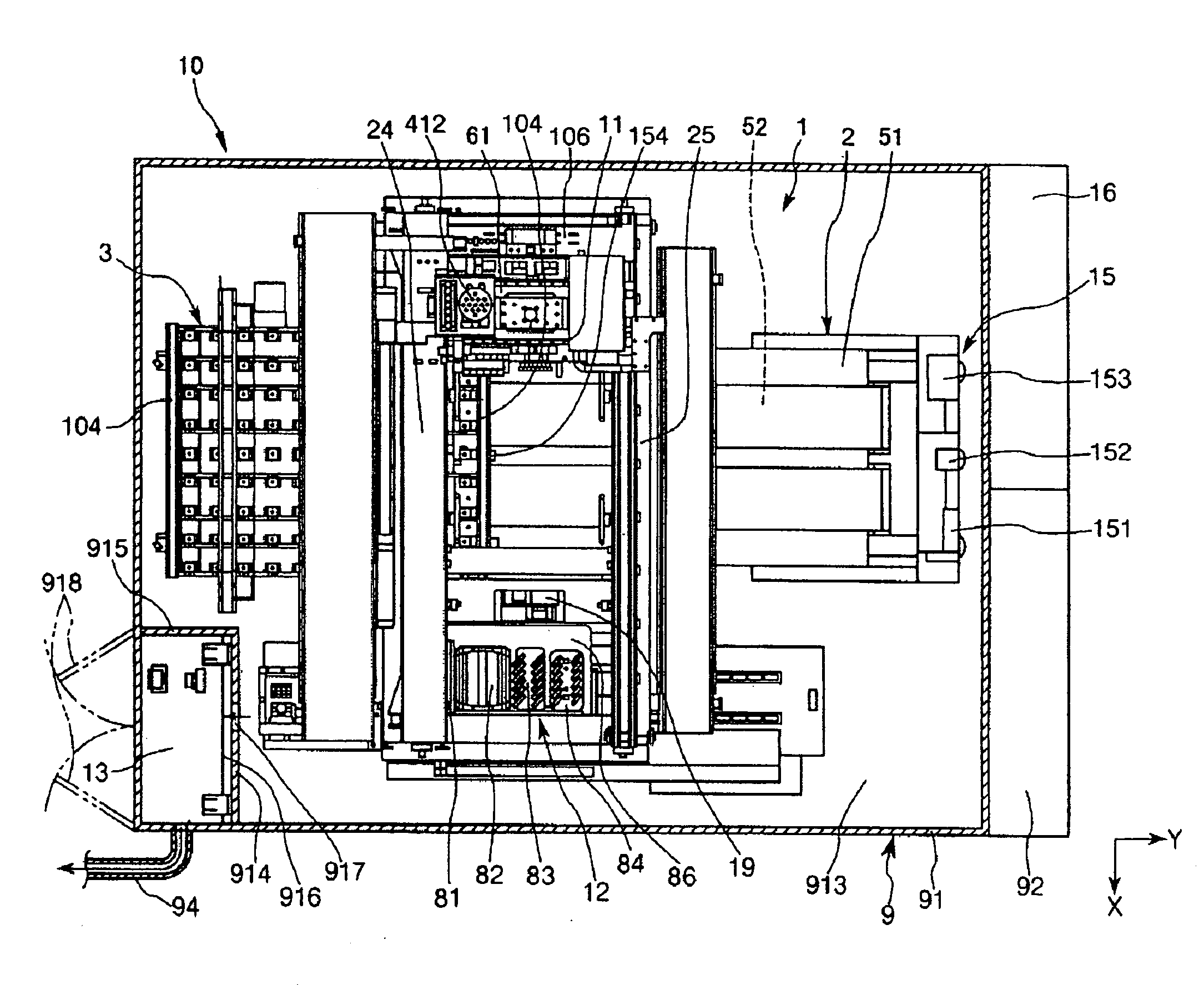
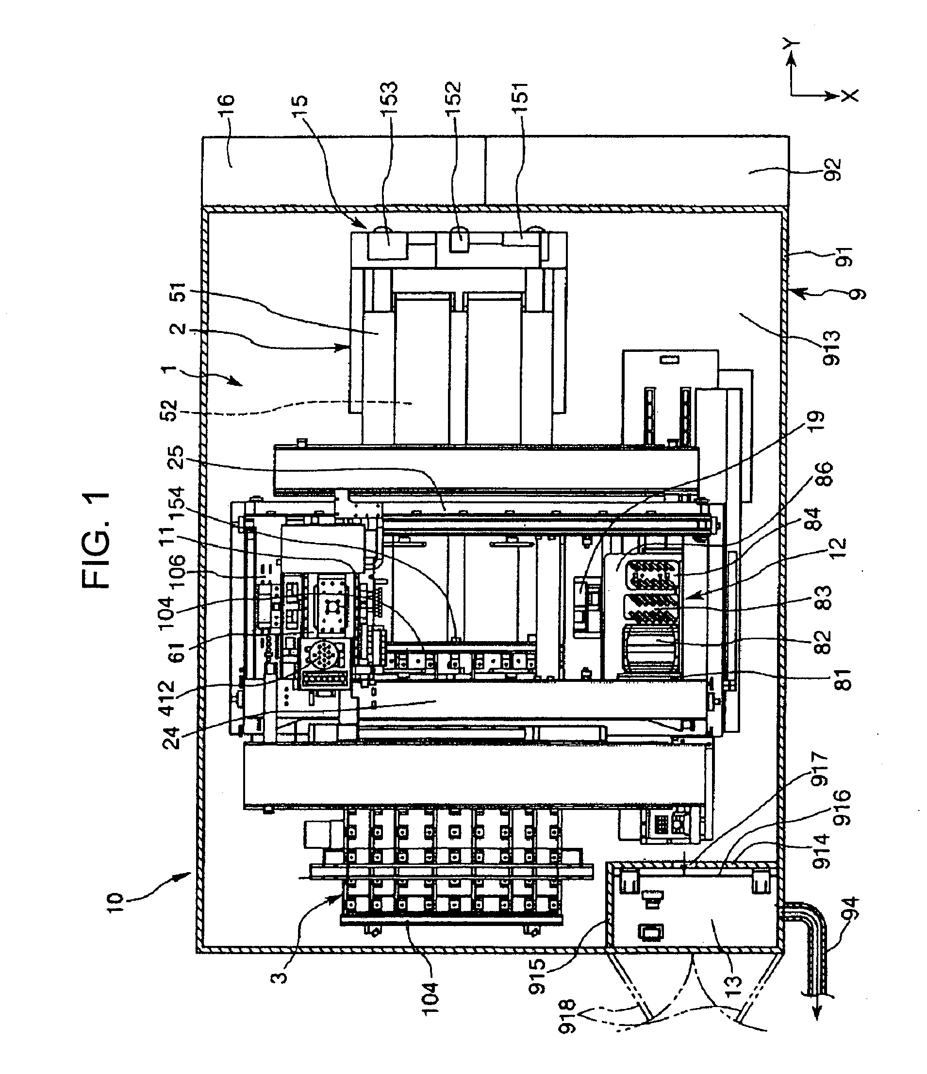
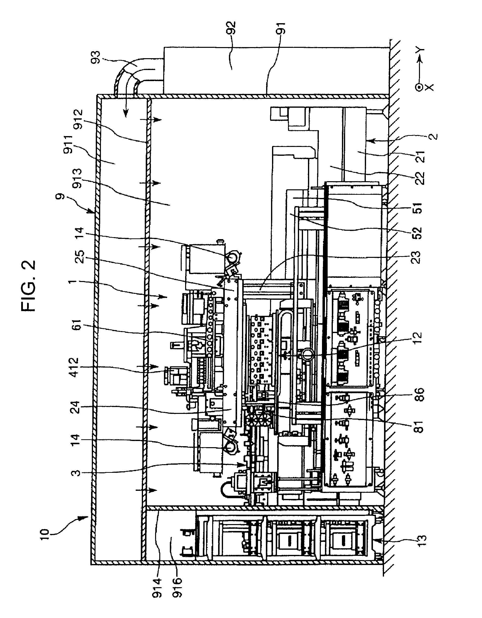
[0049]FIGS. 1 and 2 are a plan view and a side view illustrating an embodiment of a liquid droplet ejecting apparatus according to the present invention, respectively; and FIG. 9 is a perspective view illustrating a tank housing unit in the liquid droplet ejecting apparatus shown in FIGS. 1 and 2. Hereinafter, for the purpose of convenient explanation, one horizontal direction (the direction corresponding to the right-left direction in FIGS. 1 and 2) is referred to as a ‘Y-axis direction’, and another horizontal direction (the direction corresponding to an up-down direction in FIG. 1), perpendicular to the Y-axis direction, is referred to as an ‘X-axis direction’. Further, in the Y-axis direction, movement to the right in FIGS. 1 and 2 is referred to as ‘Y-axis advancement’, and movement to ...


PUM


Abstract

A liquid droplet ejecting apparatus of the present invention includes a cleaning unit, a regular flushing unit, capping unit, and an ejection-amount measuring unit as droplet ejecting head maintenance units used for function maintenance, function recovery, adjustment, or inspection of a liquid ejecting head. The droplet ejecting head maintenance units are arranged in a group in a movable platen as a maintenance-unit installing section. The movable platen is supported by an accessory stand physically separated from a main body.

Description

FIELD OF THE INVENTION[0001]The present invention relates to a liquid droplet ejecting apparatus, an electro-optical device, a method of manufacturing the electro-optical device, and an electronic apparatus.DESCRIPTION OF THE RELATED ART[0002]Industrial liquid droplet ejecting apparatuses (ink-jet imaging apparatuses) are used for manufacturing, for example, color filters for liquid crystal display devices or organic EL (electroluminescent) display devices, or for forming metal wiring lines on substrates, by adapting an ink-jet method (a liquid droplet ejecting method) for ink-jet printers[0003]In the liquid droplet ejecting apparatuses, there is a need for providing various units (hereinafter, referred to as droplet ejecting head maintenance units) used for function maintenance, function recovery, adjustment, or inspection of droplet ejecting heads (ink-jet heads). The droplet ejecting head maintenance units can include, for example, a cleaning unit for cleaning a nozzle-formed sur...

Claims


Application Information

Patent Timeline
Patent Type & Authority Patents(United States)
IPC IPC(8): B05B15/02B41J2/175B05B1/00G02B5/20H01L21/02H01L51/00H01L51/40H01L51/50H05B33/10
CPCB41J2/1652H01L21/02B41J2202/19H01L51/0005B41J2202/20H10K71/135
Inventor KOJIMA, KENJI
Owner KATEEVA
Why Eureka
Try Eureka