Radar altimeter

a technology of altimeters and antennas, applied in the field of altimeters, can solve the problems of large magnitude of antenna coupling signals, difficulty in determining the coupling amount of transmitter antennas to receiver antennas, and difficulty in determining the coupling amount of transmitter antennas. achieve the effect of more accurate altitude measurements

Inactive Publication Date: 2006-01-31
HONEYWELL INT INC
View PDF18 Cites 33 Cited by
  • Summary
  • Abstract
  • Description
  • Claims
  • Application Information

AI Technical Summary

Benefits of technology

[0013]The receiver further includes an analog-to-digital converter that converts the baseband difference signal to a digital difference signal. A digital signal processor is also provided that determines the difference frequency from the digital difference signal, and then correlates the difference frequency to the altitude of the aircraft for the particular modulation frequency of the radio signal. The receiver also includes a microprocessor that controls the variable rate modulator of the transmitter so as to vary the modulation frequency of the radio signal based on the altitude of the aircraft. Preferably, the modulation frequency of the radio signal is varied when the altitude of the aircraft reaches one or more threshold altitudes, such that the modulation frequency is greater at altitudes below a particular threshold altitude than at altitudes above the particular threshold altitude. By varying the modulation frequency of the radio signal, the receiver is able to obtain more accurate altitude measurements when the aircraft is near the ground surface.

Problems solved by technology

One inherent problem with the design of a FMCW radar altimeter is that there will be a certain amount of coupling from the transmitter antenna to the receiver antenna.
This antenna coupling is particularly problematic at higher altitudes where the magnitude of the antenna coupling signal is significant compared to the magnitude of the received reflected radio signal.
As such, the receiver will occasionally lock on to the antenna coupling signal, and then erroneously use the frequency of the antenna coupling signal to determine the altitude of the aircraft.
When this happens, the needle of the radar altimeter display drops to approximately 0 feet, resulting in undue pilot concern or even the loss of the pilot's confidence in the radar altimeter.
There are several disadvantages, however, associated with the use of a switched filter within the receiver of a FMCW radar altimeter.
As such, the switched filter may not be customized on an individual installation basis.

Method used


Image

  • Radar altimeter
  • Radar altimeter
  • Radar altimeter

Examples


Embodiment Construction

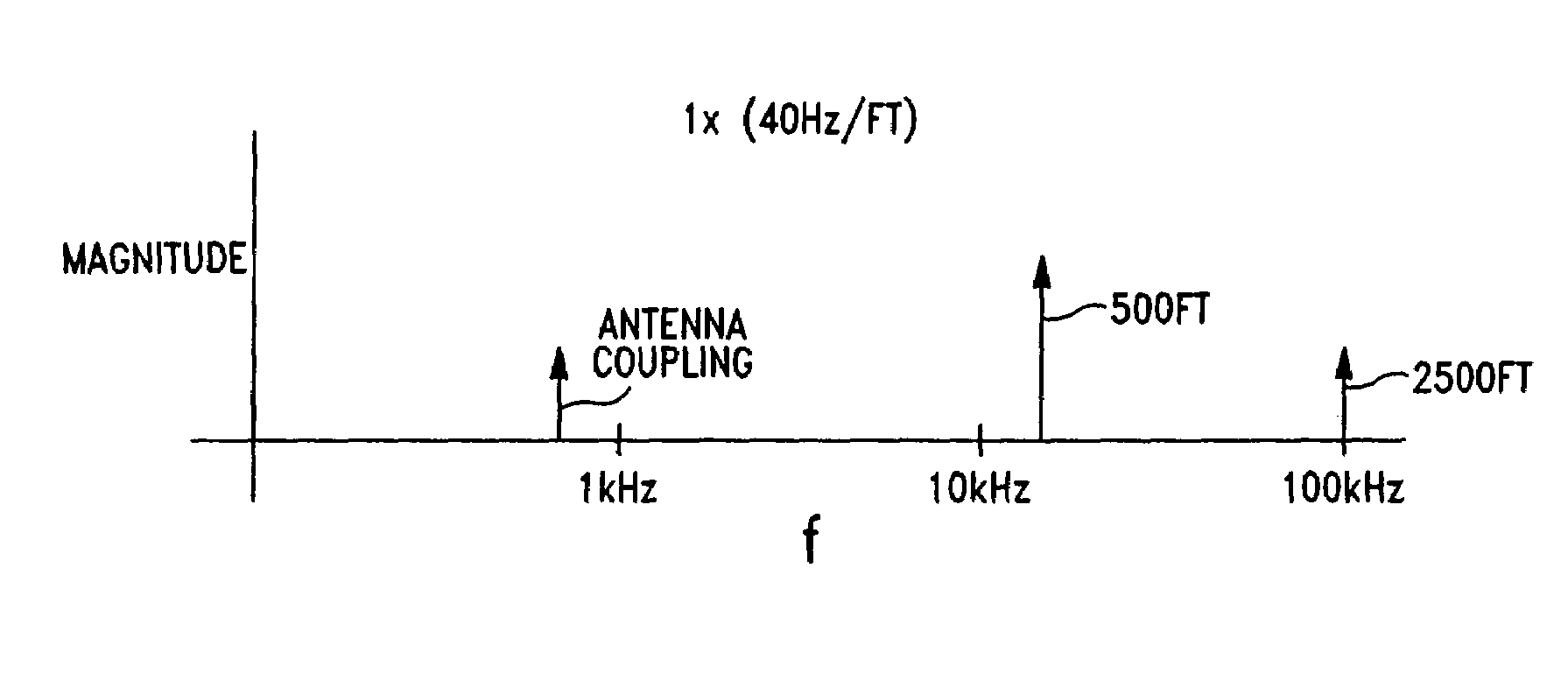
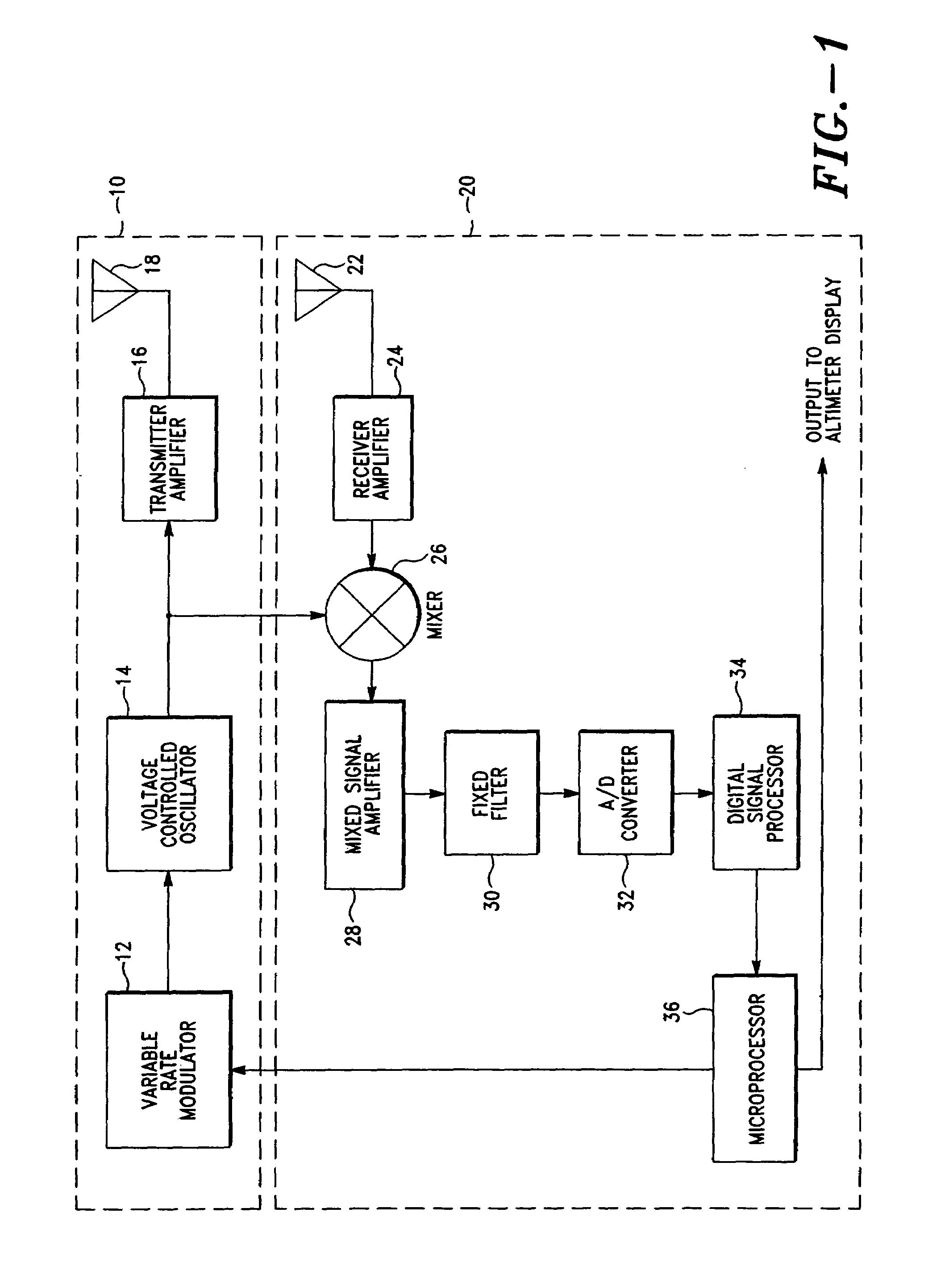
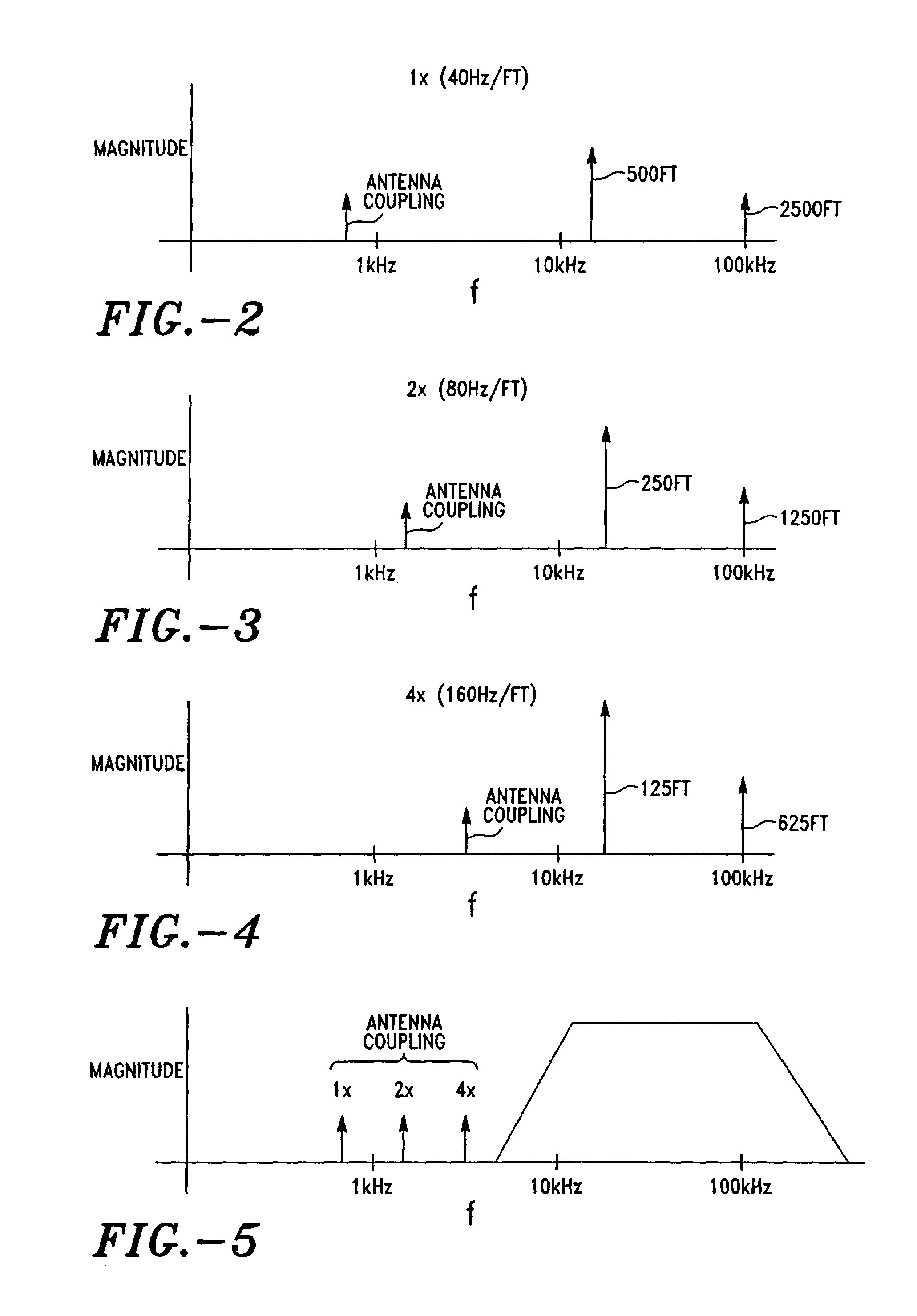
[0020]A frequency modulated continuous wave (FMCW) radar altimeter in accordance with an exemplary embodiment of the present invention is depicted in FIG. 1 (with graphical representations of the functionality of the radar altimeter depicted in FIGS. 2–5). While the invention will be described in detail hereinbelow with reference to this exemplary embodiment, it should be understood that the invention is not limited to the specific architecture of the radar altimeter shown in this embodiment. Rather, one skilled in the art will appreciate that a wide variety of radar altimeter architectures may be implemented in accordance with the present invention.

[0021]Referring to FIG. 1, a radar altimeter in accordance with an exemplary embodiment of the present invention includes a transmitter 10 (which generally comprises a variable rate modulator 12, a voltage controlled oscillator 14, a transmitter amplifier 16, and a transmitter antenna 18) and a receiver 20 (which generally comprises a re...


PUM


Abstract

A radar altimeter is provided that includes a transmitter operable to generate a radio signal at a modulation frequency, and transmit the radio signal toward a ground surface for reflection therefrom to thereby propagate a reflected radio signal. The radar altimeter also includes a receiver operable to receive the reflected radio signal, and determine the altitude of the aircraft based on the modulation frequency of the radio signal and a difference frequency derived from the radio signal and the reflected radio signal. The receiver is also operable to control the transmitter so as to vary the modulation frequency of the radio signal based on the altitude of the aircraft. Preferably, the modulation frequency of the radio signal is greater at lower altitudes than at higher altitudes.

Description

CROSS-REFERENCE TO RELATED APPLICATIONS[0001]Not Applicable.STATEMENT REGARDING FEDERALLY SPONSORED RESEARCH OR DEVELOPMENT[0002]Not Applicable.BACKGROUND OF THE INVENTION[0003]1. Field of the Invention[0004]The present invention relates generally to radar altimeters, and more particularly to frequency modulated continuous wave (FMCW) radar altimeters used for aviation navigation.[0005]2. Description of Related Art[0006]Frequency modulated continuous wave (FMCW) radar altimeters are used by pilots to determine the altitude of an aircraft in flight-critical situations, such as making an instrument landing in low visibility conditions. A FMCW radar altimeter generally comprises a transmitter that transmits a radio signal toward the ground surface, and a receiver that receives the radio signal after it has reflected from the ground surface. The receiver mixes the transmitted radio signal with the received reflected radio signal and thereby generates a difference signal. The receiver us...

Claims


Application Information

Patent Timeline
Patent Type & Authority Patents(United States)
IPC IPC(8): G01S13/32
CPCG01S7/352G01S13/34G01S13/882
Inventor JOYCE, JAMES W.
Owner HONEYWELL INT INC
Why Eureka
Try Eureka