Electronic endoscope apparatus adaptable to endoscopes equipped with imaging device with different pixel density

an endoscope and electronic technology, applied in the field of electronic endoscope equipment, can solve the problems of unavoidable waste in apparatus configuration or cost, and limit the ability to cope with diversifying pixel density

Inactive Publication Date: 2006-01-31
FUJI PHOTO OPTICAL CO LTD
View PDF7 Cites 69 Cited by
  • Summary
  • Abstract
  • Description
  • Claims
  • Application Information

AI Technical Summary

Benefits of technology

[0011]The present invention has been made in view of the above described problems, and its object is to provide an electronic endoscope apparatus which allows to conform to imaging devices with different pixel densities by use of a single processor unit, thereby avoiding any waste in terms of configuration or cost.
[0016]In this way, the present invention allows to connect an electronic endoscope having a second imaging device with a different pixel density to the processor unit which includes the first drive pulse generation circuit to drive the first imaging device with a reference pixel density in the first electronic endoscope, and also allows to perform image processing on the signals outputted from each imaging device by a single processor unit.

Problems solved by technology

However, fabricating a separate processor unit 3 to conform to each electronic endoscope 1 having a built-in CCD 2 with different pixel densities leads to unavoidable waste in terms of apparatus configuration or cost.
Moreover, there is a problem in that there are limits in coping with the diversifying pixel density of CCD 2 when various requirements of different types of electronic endoscopes 1 need to be met by means of the foregoing drive pulse generation circuit.

Method used


Image

  • Electronic endoscope apparatus adaptable to endoscopes equipped with imaging device with different pixel density
  • Electronic endoscope apparatus adaptable to endoscopes equipped with imaging device with different pixel density
  • Electronic endoscope apparatus adaptable to endoscopes equipped with imaging device with different pixel density

Examples


Embodiment Construction

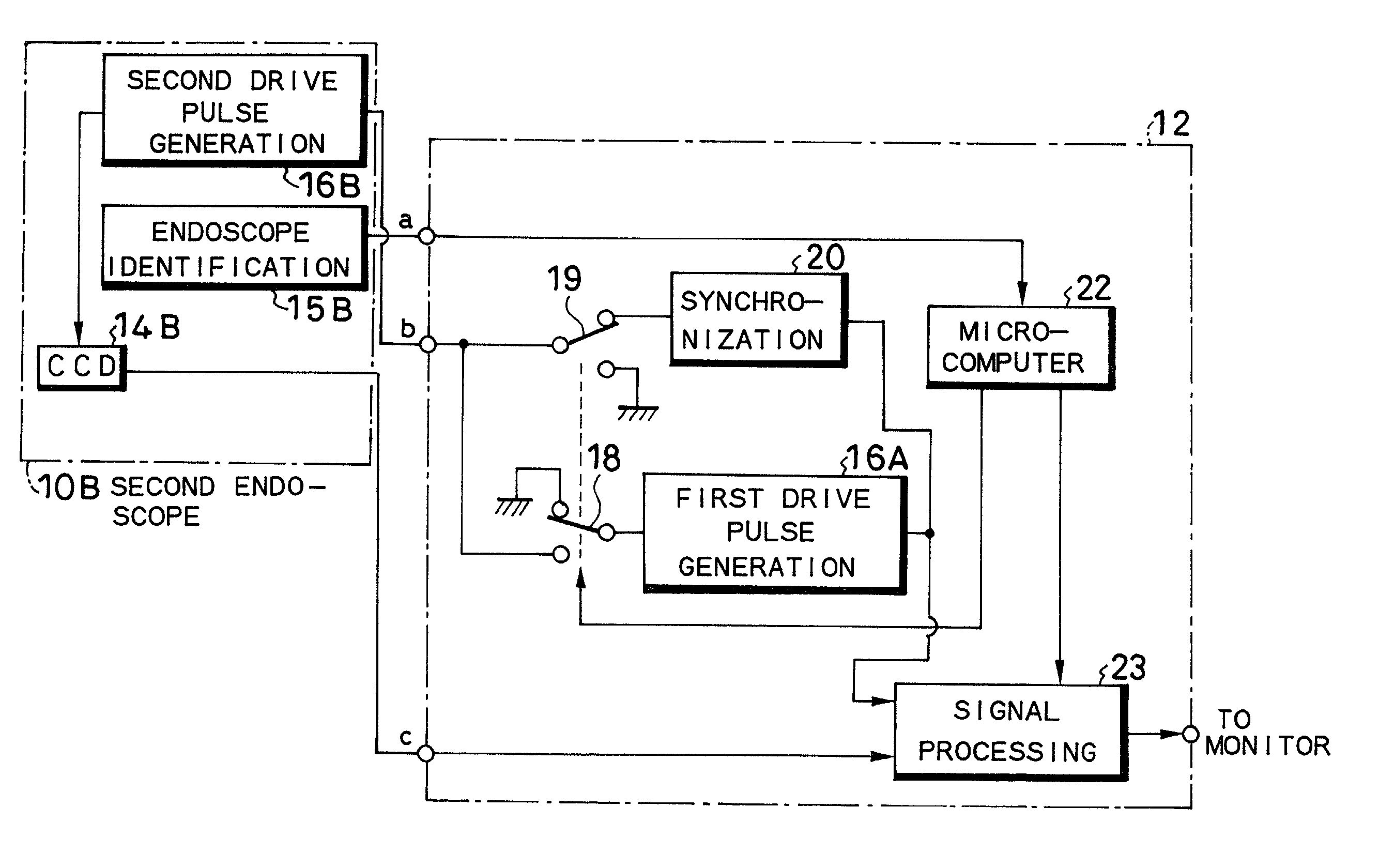
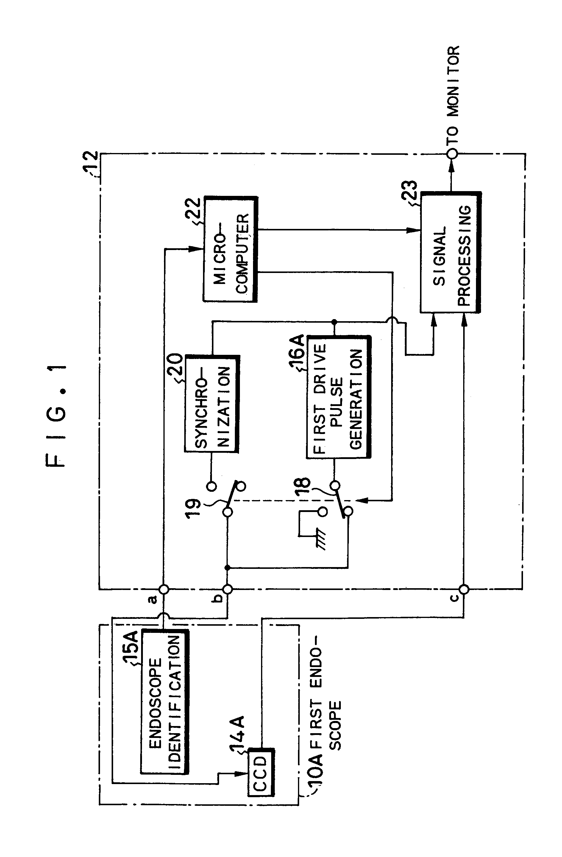
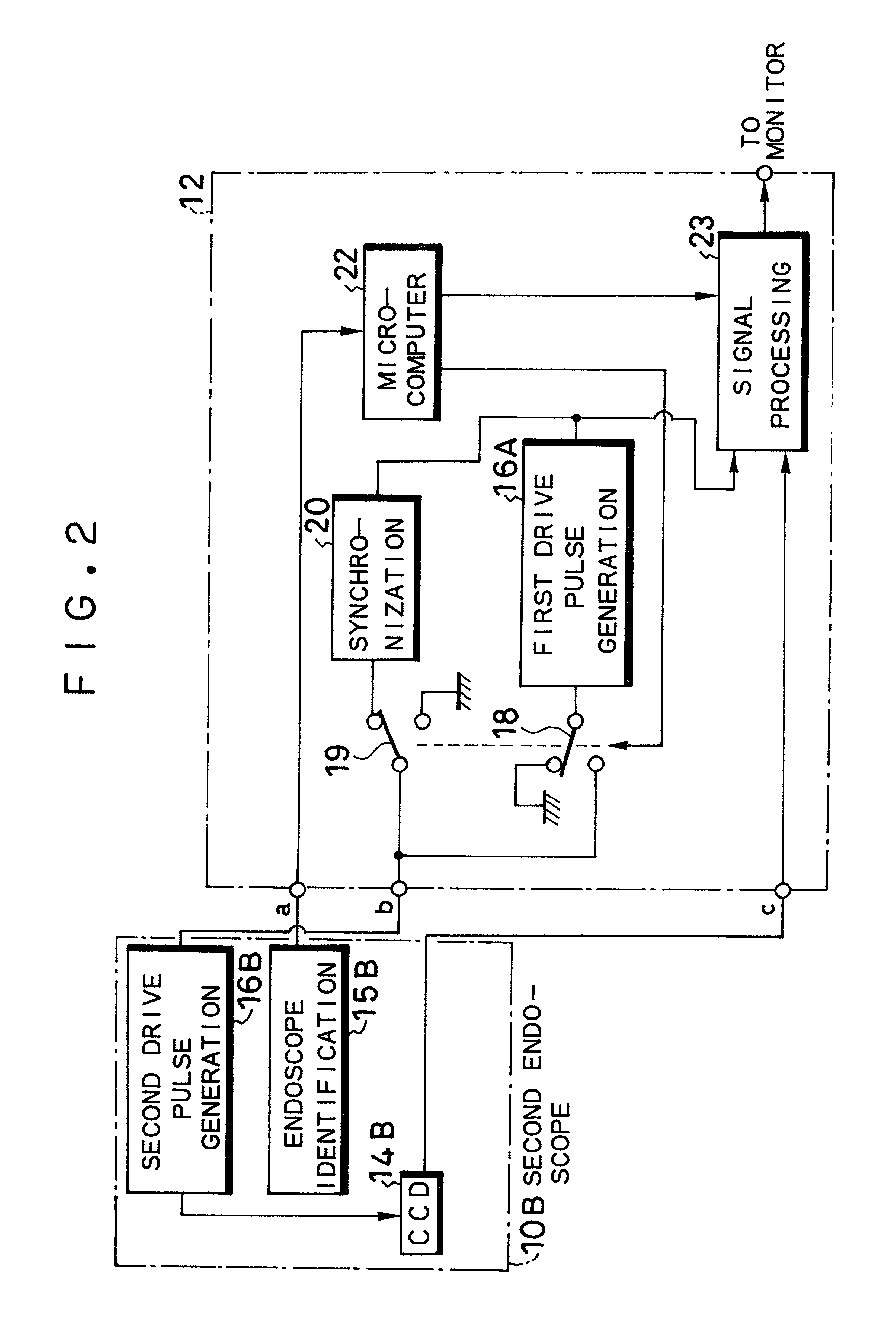
[0020]FIGS. 1 and 2 show the configuration of an electronic endoscope apparatus according to an embodiment of the present invention, and the apparatus, as shown in the figures, includes a first electronic endoscope (hereinafter referred to as endoscope) 10A and a second endoscope 10B, both of which are of a different type from one another and connectable to the processor unit 12. The first endoscope 10A in FIG. 1 includes, for example, a 410-kilo-pixel CCD 14A, which will capture the image of the object to be observed through an object lens system. Furthermore, the first endoscope 10A includes a endoscope identifying information generation module 15A. In this embodiment, identifying information which is specific to each endoscope and recorded on a storage medium such as an EEPROM is sent out by communication means, and the identifying information is read out and interpreted by a microprocessor 22 on the processing unit, which will be described later. It is also possible to use a sha...


PUM


Abstract

An electronic endoscope apparatus including: a first endoscope having a first imaging device; and a second endoscope having a second imaging device with a different pixel density and a second drive pulse generation circuit, wherein a processor unit, which connects the two endoscopes, comprises: a first drive pulse generation circuit for driving the first imaging device, a synchronization circuit for generating a synchronizing signal synchronous with the signal of the second drive pulse generation circuit, a switching circuit for activating the synchronization circuit when the second endoscope is connected, and a signal processing circuit for processing the signals obtained by the first imaging device and for processing the signals obtained by the second imaging device based on the synchronizing signal. By this configuration, a single processor unit will suffice even when employing an imaging device with a different pixel density.

Description

BACKGROUND OF THE INVENTION[0001]This application claims the priority of Japanese Patent Applications No. 2001-1828 filed on Jan. 9, 2001 which is incorporated herein by reference.[0002]1. Field of the Invention[0003]The present invention relates to an electronic endoscope apparatus, specifically to a configuration of an electronic endoscope apparatus wherein electronic endoscopes having an imaging device with different pixel densities are connected to a common processor unit.[0004]2. Description of the Prior Art[0005]FIG. 3 shows the configuration of a part of a conventional electronic endoscope apparatus and, as shown in the figure, a CCD (Charge Coupled Device) 2, which is a solid-state imaging device, is disposed at the tip of an electronic endoscope 1. The endoscope 1 is configured to connect detachably to a processor unit 3, and the processor unit 3 is provided with a drive pulse generation unit 4 for generating drive pulses to drive the CCD 2 and a signal processing circuit 5...

Claims


Application Information

Patent Timeline
Patent Type & Authority Patents(United States)
IPC IPC(8): H04N7/18G02B23/24A61B1/04H04N5/04H04N5/225H04N5/232H04N5/335H04N5/372H04N5/376
CPCH04N5/04H04N5/335H04N5/23209H04N2005/2255H04N23/555H04N23/663H04N25/00
Inventor ABE, KAZUNORI
Owner FUJI PHOTO OPTICAL CO LTD
Why Eureka
Try Eureka