Illuminating apparatus, display panel, view finder, video display apparatus, and video camera mounting the elements

a technology of video display and elements, which is applied in the direction of optical elements, television systems, instruments, etc., can solve the problems of deteriorating light utilization efficiency, affecting the efficiency of light utilization, and the size of the conventional backlight b>861/b> is too large to reduce the size and weight of the equipment,

Inactive Publication Date: 2006-01-31
PANASONIC CORP
View PDF13 Cites 362 Cited by
  • Summary
  • Abstract
  • Description
  • Claims
  • Application Information

AI Technical Summary

Benefits of technology

[0083]In a video display apparatus according to another embodiment of the invention, for example, a monitor window of standard white or black display is formed. The obser

Problems solved by technology

Even when a liquid crystal display panel of lower power consumption is used, if the power consumption of the backlight is large, the power consumption of the whole video equipment is not low.
There is also a problem that the size of the conventional backlight 861 is too large to reduce the size and weight of the equipment.
As to the conventional view finder, there is also a problem that a diffuser 862

Method used


Image

  • Illuminating apparatus, display panel, view finder, video display apparatus, and video camera mounting the elements
  • Illuminating apparatus, display panel, view finder, video display apparatus, and video camera mounting the elements
  • Illuminating apparatus, display panel, view finder, video display apparatus, and video camera mounting the elements

Examples


Embodiment Construction

[0479]Embodiments of the invention will be described hereinbelow with reference to the drawings.

[0480]For mainly simplicity of explanation, the drawings includes omitted parts, exaggerated parts, and enlarged or reduced parts or the like.

[0481]Component elements to which the same reference numerals are designated have the same or similar configuration otherwise than specifically described. Parts and configuration which does not need to be explained are therefore omitted here.

[0482]Since mirrors 342, 271, and 261 have the same or similar configuration and function, they can be replaced with each other. Similarly, pixels 341 and 181 can be also replaced with each other.

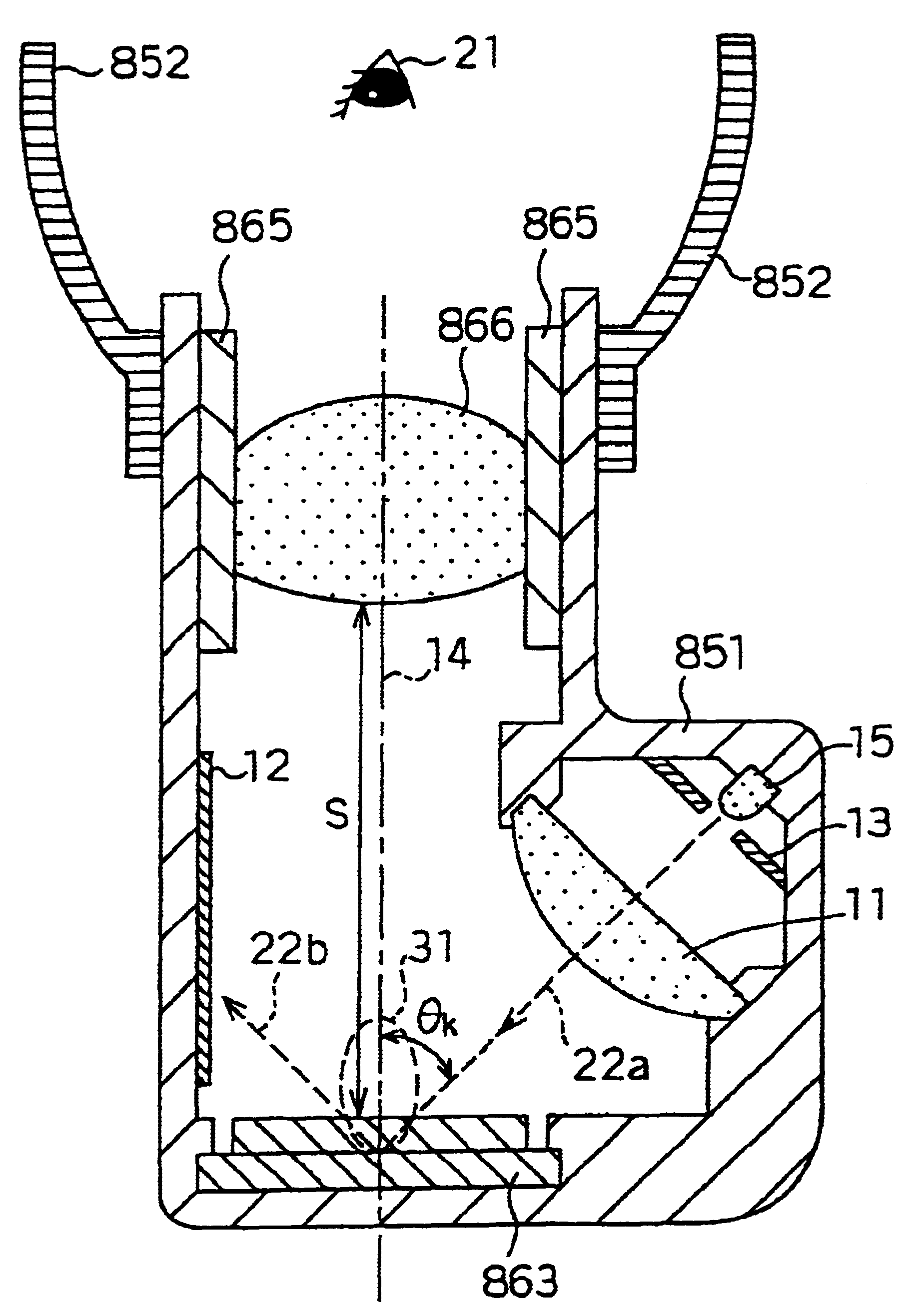
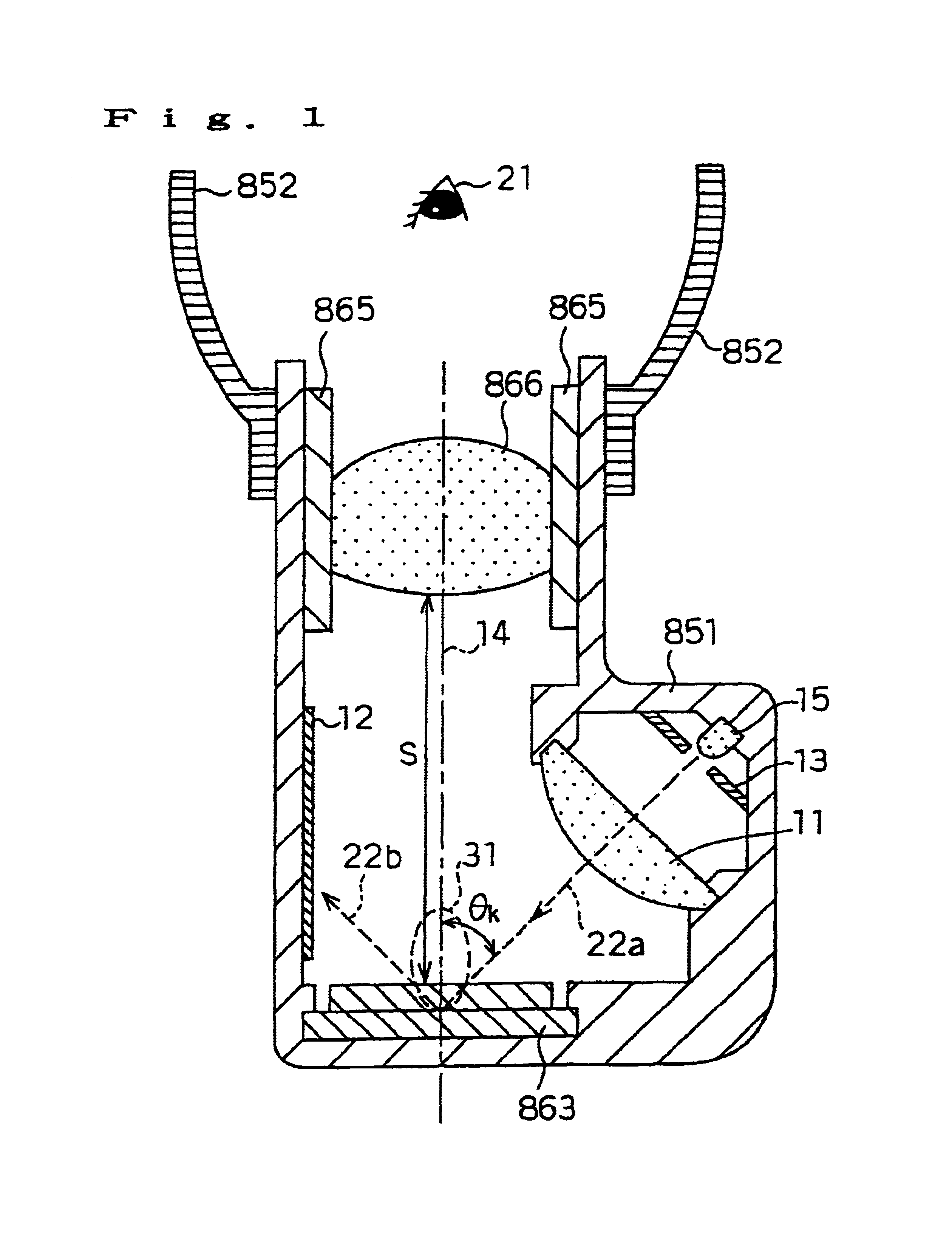
[0483]FIG. 1 is a cross section of a view finder of the invention. A white LED 15 is disposed in the body 851. The LED can emit white light and is sold by Nichia Corporation. Obviously, an LED of a single color (green, red, blue, yellow, orange, or the like) may be used or LEDs of a plurality of colors may be combined a...


PUM

PropertyMeasurementUnit
Angleaaaaaaaaaa
Transparencyaaaaaaaaaa

Abstract

Light emitted from a white LED 15 is converted by a lens 11 into light having an excellent directionality. The light illuminates a display panel 863 from the direction of an angle θk. The display panel 863 is a polymer dispersed liquid crystal display panel in a normally white mode. The display panel 863 modulates incident light by scattering it, the scattered light is incident on a magnification lens 866, and light from the magnification lens reaches an eye 21 of the observer. Light which passes straight through a liquid crystal layer in the display panel 863 is absorbed by an optical absorbing film 12. The observer fixedly positions his/her eye 21 to an eyepiece cover 852 and observes the displayed image.

Description

BACKGROUND OF THE INVENTION[0001]1. Field of the Invention[0002]The present invention relates to an illuminating apparatus and a display panel which are used for a video camera or the like, a view finder and a video camera which use the illuminating apparatus, a video display apparatus, a method of driving the display panel, and the like.[0003]2. Description of the Related Art[0004]A conventional view finder will be first described. In the specification, an element in which at least a light source (light generating means) such as a light emitting device and an image display apparatus (light modulating means) such as a liquid crystal display panel, not of a self light emitting type are integrally formed is called a view finder.[0005]The appearance of a view finder is shown in FIG. 85 as an example. A cross section of the conventional view finder is illustrated in FIG. 86. Shown in the diagrams are the body 851, an eyepiece cover 852, an eyepiece ring 865, and a display panel 863 such...

Claims


Application Information

Patent Timeline
IPC IPC(8): H04N5/222
CPCG02B23/14G02B27/026G02F1/133553G02F1/1334G02F1/133514G02F2001/133616G02F1/133526G02F1/133603G02F1/133524G02F1/133616
Inventor TAKAHARA, HIROSHI
Owner PANASONIC CORP
Why Eureka
Try Eureka