Image pickup device attachable to electronic apparatus

a technology for electronic equipment and image pickup, which is applied in the field of peripheral equipment, can solve the problems of insufficient conventional configuration of ccd cameras and too large image pickup portions, so as to reduce the load, prevent the deterioration of the connector, and reduce the load

Inactive Publication Date: 2006-01-31
FUJITSU LTD +1
View PDF20 Cites 41 Cited by
  • Summary
  • Abstract
  • Description
  • Claims
  • Application Information

AI Technical Summary

Benefits of technology

[0009]Another exemplified and more specific object of the present invention is to provide an image pickup device attachable to an electronic apparatus that can prevent the connector portion from breaking while ensuring its connectivity with universal notebook PCs.
[0010]In order to achieve the above objects, an image pickup device as one exemplified, embodiment of the present invention comprises a connector which is connectible, e.g., electrically or optically, to an electronic apparatus, and a reinforcing portion which is located near the connector and reinforces the connector when the electronic apparatus and the connector connect with each other. The reinforcing portion in this image pickup device may reduce a load that would otherwise apply to the connector, and prevent connector's deterioration in the course of time.
[0011]The image pickup device may further comprise an anchor portion and a movable portion. The movable portion includes an image pickup portion, and the connector and the reinforcing portion may be placed on the anchor portion. The reinforcing portion can be stored in the anchor portion so that it can project from the anchor portion. Accordingly, the reinforcing portion may be stored in the anchor portion while the image pickup device is not attached to the electronic apparatus. The image pickup device may further comprise a stand that is connected with the anchor portion and serves to adjust a height of the anchor portion. Consequently, the height of the image pickup device can be varied according to a height of the electronic apparatus to which the image pickup device is attached, reducing a load applied that would otherwise apply to the connector when the electronic apparatus having the image pickup device is placed on its footprint. The stand may adjust an inclined angle of the anchor portion. Therefore, for example, even if the electronic apparatus is a notebook PC of which a keyboard tilts for ergonomic purposes, a position and orientation of the anchor portion of the image pickup device can be adjusted accordingly, whereby the load to the connector would be eliminated as well. The anchor portion may include a storage portion that can store the image pickup portion. This allows the image pickup device to protect the image pickup portion when unused.
[0012]The image pickup device as another exemplified embodiment of the present invention comprises a connector that is connectible, e.g., electrically or optically, to an electronic apparatus, and an attachment portion that enables the image pickup device to be attached to an external apparatus. This image pickup device may be attached to an external device (including electronic apparatus) through the attachment portion. Thus, the image pickup device attached to a desired position may capture a desired subject, and to remove or reduce an area for placement of the image pickup device. The image pickup device may include an anchor portion and a movable portion. The movable portion includes an image pickup portion, and the connector may be placed on the anchor portion. The attachment portion enables the anchor portion to be attached to the external apparatus. The attachment portion may be provided onto the anchor portion so that it can project from the anchor portion. Accordingly, the attachment portion may be attached to any position, for instance, the electronic apparatus may include a display portion, and the image pickup device may be attached onto the display portion through the attachment portion.

Problems solved by technology

However, an image pickup portion including an image-pickup lens is still too large for portability.
In this respect, conventional configurations for the CCD camera are not sufficient so as to prevent the connector portion such as a USB port from breaking while ensuring its connectivity with universal notebook PCs.

Method used


Image

  • Image pickup device attachable to electronic apparatus
  • Image pickup device attachable to electronic apparatus
  • Image pickup device attachable to electronic apparatus

Examples


Embodiment Construction

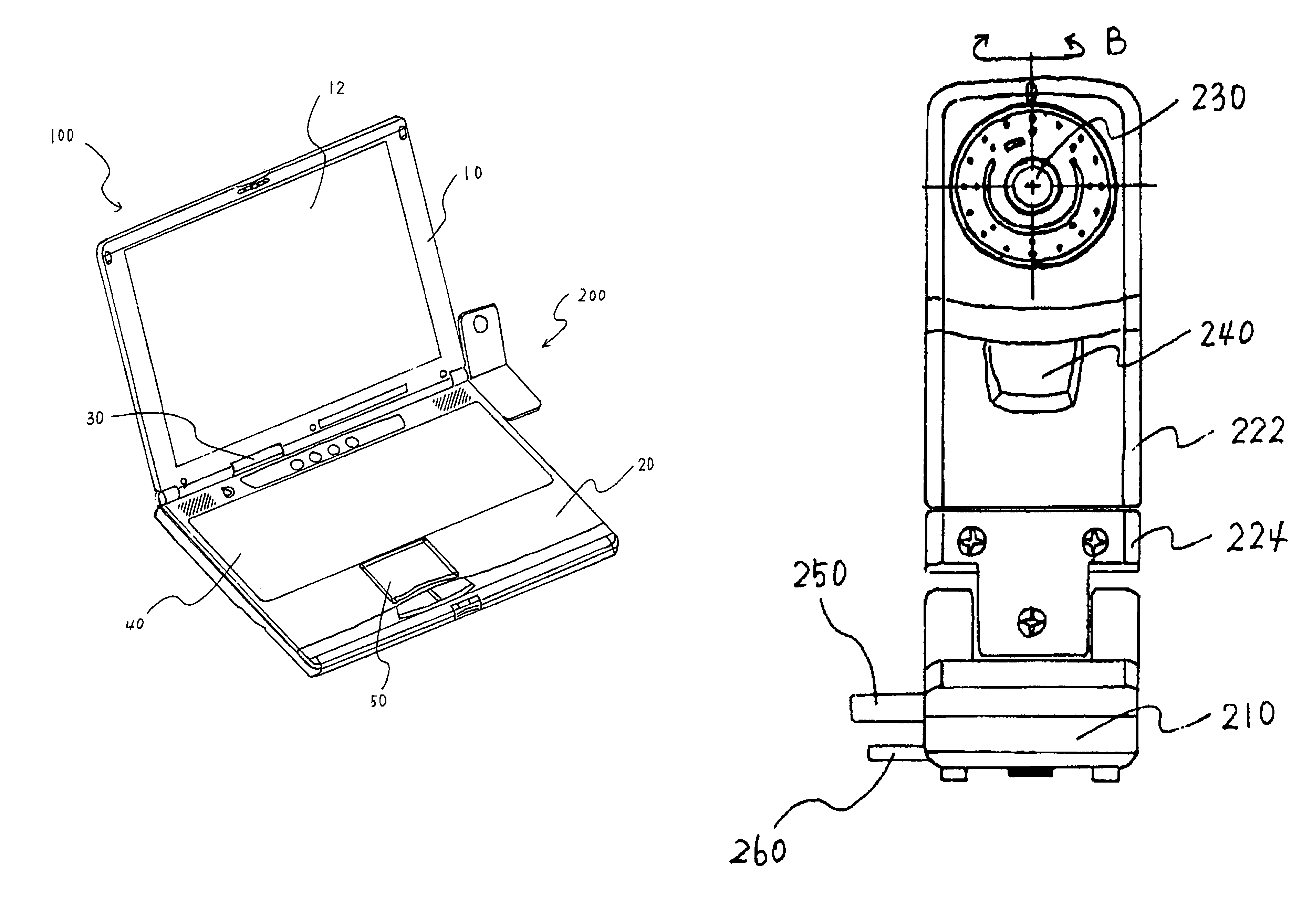
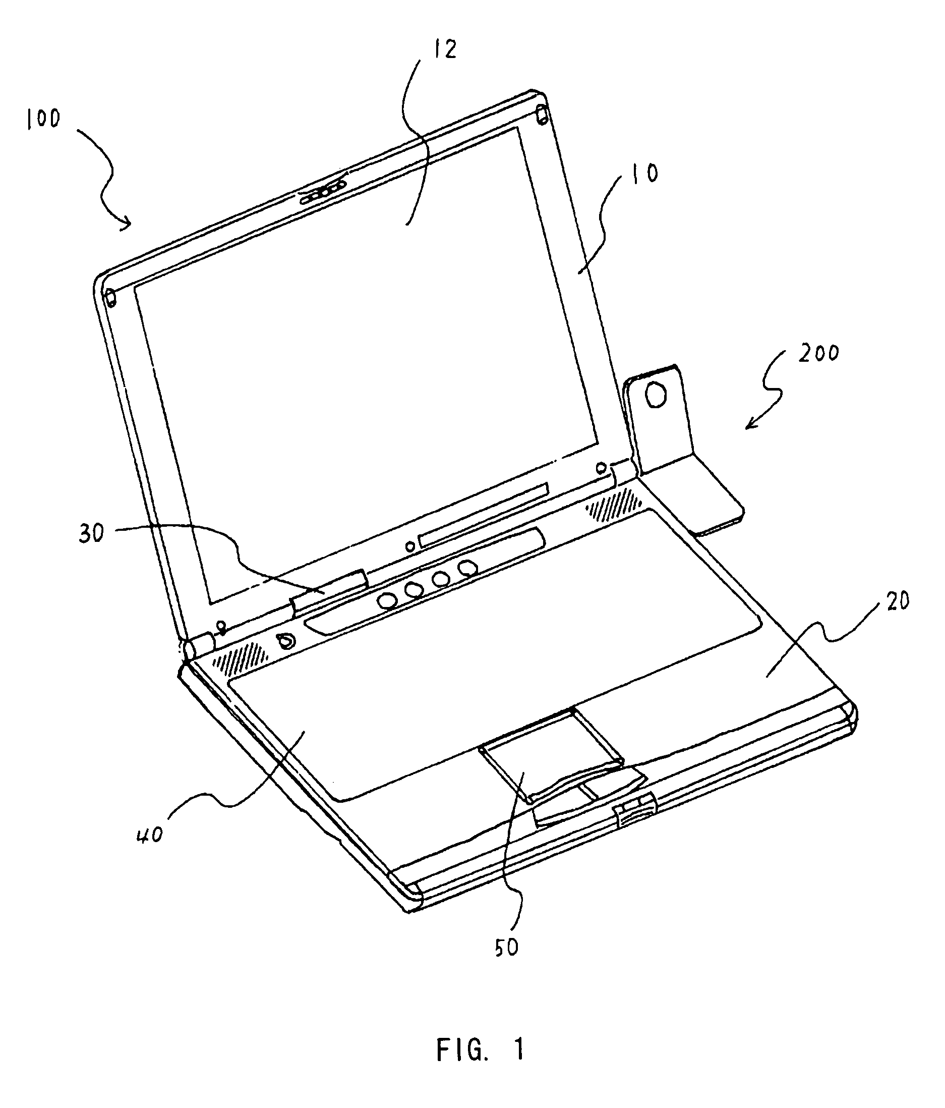
[0032]A description will now be given of an inventive image pickup device 100 connected to an electronic apparatus 100 with reference to FIG. 1. The same members are designated by the same reference numerals, and a duplicate description thereof will be omitted.

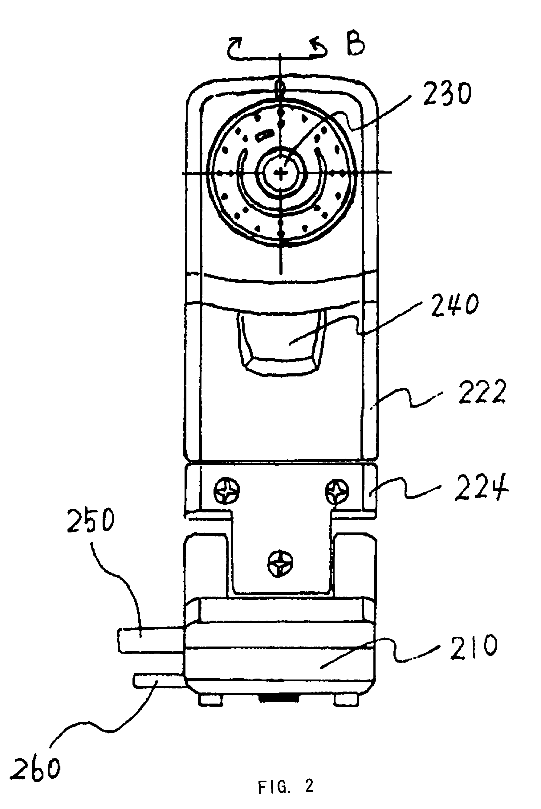
[0033]Referring to FIG. 1, an electronic apparatus 100 and the image pickup device 200 are exemplarily shown as, but not limited to, a notebook PC 100 and a CCD camera 200, respectively. The electronic apparatus 100 includes PDAs, handheld PCs, palm-size PCs, wearable computers, portable electronic apparatuses, and portable terminals. The image pickup device 200 includes, but not limited to, digital still cameras, digital movie cameras, disc cameras, digital video cameras, retina recognition devices, fingerprint recognition devices, and the like. The notebook PC 100 may cover A4, B5, sub-notebook, mini-notebook and other sizes. Hereupon, FIG. 1 is a schematic perspective view of the CCD camera 200 mounted on the notebook PC 10...


PUM


Abstract

The present invention aims at providing a function-expansion unit for an electronic apparatus that may reduce the stress onto a connector, and provides a high stability with a CCD camera. The CCD camera includes a reinforcing member under its connecting portion and a height-adjustable stand, thereby reducing the stress that would otherwise apply to the USB connector as the connecting portion, enhancing the connection, preventing connector's deterioration in the course of time, and allowing the CCD camera to be stably placed.

Description

BACKGROUND OF THE INVENTION[0001]The present invention relates generally to peripheral equipment for use with a notebook personal computer (“notebook PC”) or portable terminal, a portable electronic apparatus, a personal digital assistant (“PDA”), and other electronic apparatuses, and more particularly to an image pickup device connectible with the electronic apparatus or hardware. The “peripheral equipment”, as used herein, is such hardware as is connectible with a PC body and realizes necessary functions.[0002]The recent development and spread of notebook PCs, portable terminals and portable electronic apparatuses have increasingly demanded compact and lightweight notebook PCs for portability purposes which nevertheless exhibit such affluent functions on a desk in an office as desktop personal computers (“desktop PCs”). As part of an attempt to achieve such multi-functionality, a device for adding an image pickup function to the notebook PC has been proposed.[0003]Japanese Laid-Op...

Claims


Application Information

Patent Timeline
Patent Type & Authority Patents(United States)
IPC IPC(8): H04N5/225G06F15/02G06F1/16
CPCG06F1/1607H04N5/2252G06F1/1686G06F1/1632H04N23/51
Inventor KAMBAYASHI, KOHIRASAWA, TAKASHI
Owner FUJITSU LTD
Why Eureka
Try Eureka