Closed circuit television camera

a closed circuit television and camera technology, applied in the field of closed circuit television ccd, can solve the problems of cumbersome installation, insufficient protection, and inability to provide adequate protection, and achieve the effects of time-consuming and labor-intensive, and reducing the cost of installation

Inactive Publication Date: 2006-01-31
JUNG WOONKI
View PDF2 Cites 32 Cited by
  • Summary
  • Abstract
  • Description
  • Claims
  • Application Information

AI Technical Summary

Benefits of technology

[0010]The present invention includes: a pre-assembled Closed Circuit Television CCD (camera), a housing base formed to receive support rods, a housing cover with glass window which is joined to the base with an variable focal auto iris lens, a lens mount coupler for receiving the lens and attaching to the housing base, AC-to-DC converter (analog to digital voltage converter), mounted on a circuit board. There may also be circuit boards for the CCD components and the power circuitry. The circuit boards are joined with several support rods and fasteners, such as screws, on one end and threaded openings to receive screws on the opposite end. The lens has a key stud which is received by a slot in the coupler to prevent movement of the iris after installation. The components are protected by the complete housing with o-rings, washers, epoxy and a polyethylene sponge making a water-tight seal. The video and power cable extends from the rear of the housing base and is inserted and extended through a bushing and nut mounted inside the housing base which seals the entry point. The housing cover is also secured with tamper-proof screws. A sun shield may be included and placed on the outside of the housing base and cover to provide additional coverage of the housed camera from sun, rain and snow.

Problems solved by technology

Problems encountered with existing security cameras, their housing and mounting designs include that they a cumbersome to install, not durable and do not provide adequate protection from the weather.
Many of the present security cameras are difficult and time-consuming to assemble and install.

Method used


Image

  • Closed circuit television camera
  • Closed circuit television camera
  • Closed circuit television camera

Examples


Embodiment Construction

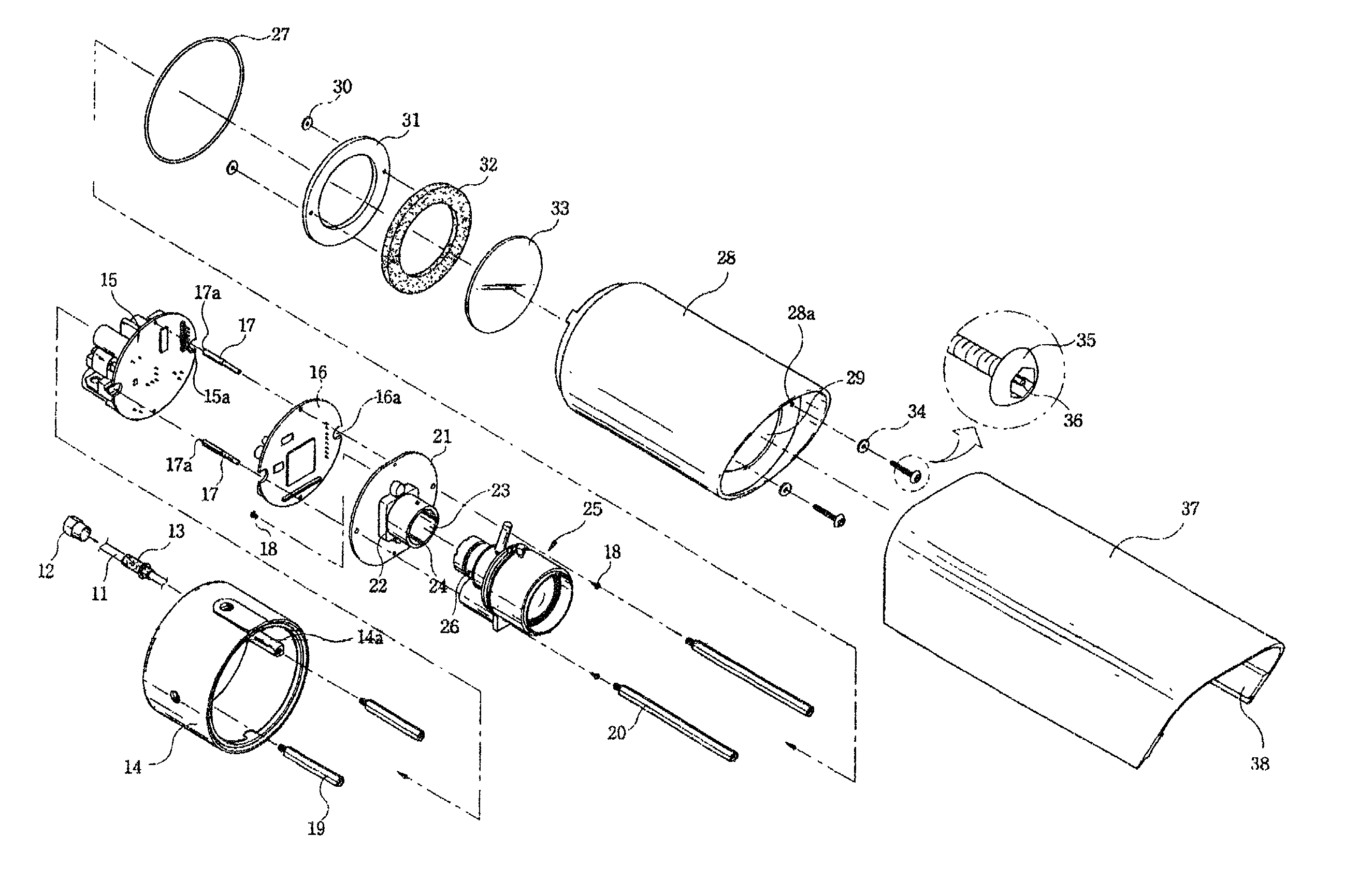
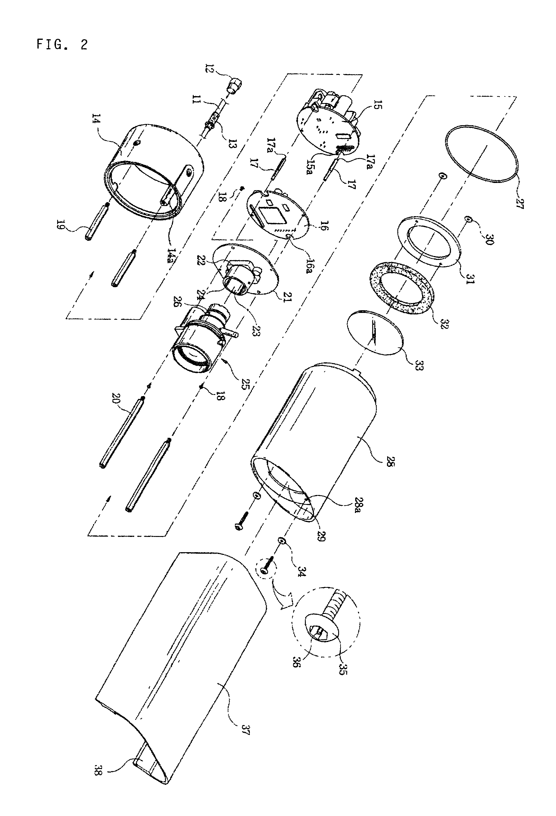
[0011]The complete CCD camera assembly of the present invention is shown in FIG. 1 which includes: the housing base 14, the housing cover 28, the variable focal auto iris lens 25, the housing cover window 29, CCD circuit board 21, the power circuit board 16, the AC-DC converter board 15 and the power input and video output cable 11. The camera assembly is generally elongated and compact. Each of the afore-mentioned components are assembled in a layered fashion and are designed to fit within each other to minimize the size of the unit.

[0012]The housing cover 28 provides coverage of the CCD camera circuitry and lens. The housing cover 28 has a housing cover window 29 and an overhanging lip 28A to protect the glass 33 and the variable focus iris 25. The glass 33 permits the image to be viewed through the opening 29 of the housing cover 28.

[0013]The components are attached to each other using a series of support rods 17, 19, and 20 or “stand offs” which are formed in the preferred embod...


PUM


Abstract

An integrated Closed Circuit Television (“CCD”) camera assembly is disclosed which is compact, weather resistant and tamper-proof. The camera assembly includes a housing base, a housing cover, a variable focal iris lens, a glass window, a CCD circuit board, an AC-to-DC converter circuit board, and a power input and a video output combined as a single cable. The components are attached to each other with a number of support rods which are inserted through each of the components and fastened with screws. The connection is sealed with o-rings, washers, a sponge and epoxy to protect the unit from moisture and dust. Tamper-proof screws are used to minimize the danger of human interference. A sun shield which is placed over the housing cover may also be used providing further protection from the elements.

Description

BACKGROUND OF THE INVENTION[0001]The present invention relates to Closed Circuit Television CCD (Charge-couple device) cameras. It is desirable to have a combined unit which includes a CCD camera, housing, and lens suitable for use in various security monitoring applications. It is further desirable to have a combined unit which readily permits surveillance of various areas, both indoors and outdoors, and in all types of weather conditions. Security cameras may be used to monitor stationary and moving targets and are usually mounted out of reach of persons in the vicinity, but at the same time are normally exposed to view. It is an object of the present invention to provide a camera unit which is easy to install, readily adjustable for different views, and easily maintainable while being aesthetically-pleasing and not subject to vandalism.[0002]Problems encountered with existing security cameras, their housing and mounting designs include that they a cumbersome to install, not durab...

Claims


Application Information

Patent Timeline
Patent Type & Authority Patents(United States)
IPC IPC(8): H04N5/225
CPCG08B13/19619H04N5/2252G08B13/19632H04N23/51H04N23/00
Inventor JUNG, WOONKI
Owner JUNG WOONKI
Why Eureka
Try Eureka