
Ferroelectric storage device

a storage device and ferroelectric technology, applied in the field of storage devices, can solve the problems of reducing the reliability of ferroelectric memories, affecting and rewriting failures, so as to improve the accuracy of reading stored data

Inactive Publication Date: 2006-01-31
PANASONIC CORP
View PDF6 Cites 6 Cited by
  • Summary
  • Abstract
  • Description
  • Claims
  • Application Information

AI Technical Summary

Benefits of technology

"The present invention provides a ferroelectric memory that can shorten the time required for rewriting and improve reliability during data rewriting. This is achieved by a write-time control circuit that changes the length of the write-time based on the level of the write-voltage applied to the ferroelectric capacitor. Additionally, the invention includes a write-voltage applying circuit that can apply different write-voltages to each ferroelectric capacitor to improve the accuracy of reading stored data. The invention can be used in a read / write unit or a separate individual unit and can be used in a ferroelectric memory that stores three or more values. Overall, the invention enhances the speed and reliability of ferroelectric memory."

Problems solved by technology

However, the ferroelectric memories can be rewritten only a limited number of times, because fatigue and deterioration of their ferroelectric films gradually progress as the memories are rewritten repeatedly.
However, if the time for the rewriting is shortened, a rewriting failure might occur.
This decreases the reliability of the ferroelectric memories.

Method used


Image

  • Ferroelectric storage device
  • Ferroelectric storage device
  • Ferroelectric storage device

Examples


first embodiment

1. The First Embodiment

[0035]A ferroelectric memory according to the first embodiment is a ferroelectric memory that stores two values, namely “1” and “0”, with use of the asymmetric programming method.

1-1. The Structure of the Ferroelectric Memory

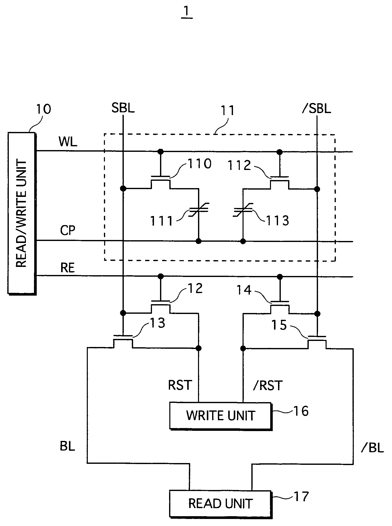
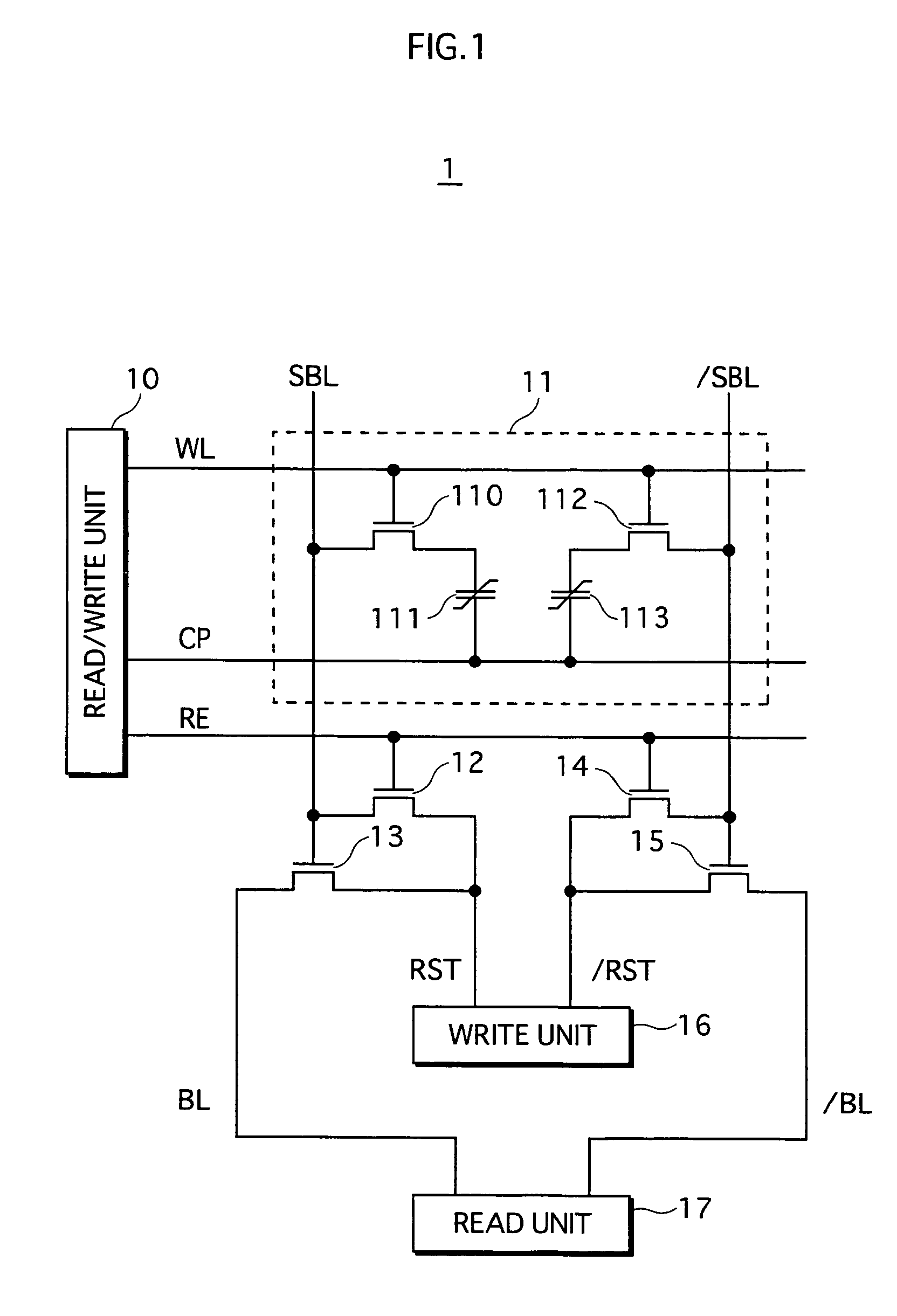
[0036]FIG. 1 shows a circuit structure of a memory cell included in the ferroelectric memory according to the first embodiment, and peripheral circuits. As FIG. 1 shows, a memory cell 11 included in a ferroelectric memory 1 stores information with use of two field-effect transistors 110 and 112, and two ferroelectric capacitors 111 and 113. This circuit structure is called 2T2C-type structure. The ferroelectric memory 1 includes, as the peripheral circuits, a read / write unit 10, a write unit 16, a read unit 17, and transistors 12 to 15.

[0037]The read / write unit 10 drives a word line WL, a memory cell plate line CP, and a reading control line RE. The write unit 16 drives reset control lines RST and / RST. The read unit 17 drives bit lines BL...

second embodiment

2. The Second Embodiment

[0061]A ferroelectric memory according to the second embodiment is a ferroelectric memory that stores four values with use of the asymmetric programming method.

2-1. The Structure of the Ferroelectric Memory

[0062]FIG. 7 shows a circuit structure of a memory cell included in the ferroelectric memory according to this embodiment, and peripheral circuits. As FIG. 7 shows, a memory cell 31 included in a ferroelectric memory 3 stores two-bit information with use of a field-effect transistor 310, and a ferroelectric capacitor 311. This circuit structure is called 1T1C (one transistor, one capacitor)-type structure. In the second embodiment, the two-bit information is stored by the ferroelectric memory 3 with use of four polarization states, namely “a”, “b”, “c” and “d.”

[0063]Also, the ferroelectric memory 3 includes, as peripheral circuits, a read / write unit 30, a read unit 34, a write unit 35 and transistors 32 and 33. The read / write unit 30 drives a word line WL, ...


PUM


Abstract

In the present invention, a polarization having a lower polarization level than a saturation polarization is caused in a ferroelectric capacitor by applying a voltage that is lower than a saturation voltage to the ferroelectric capacitor. This allows a storage device to store many values by changing a length of a write-time during which the voltage is applied to the capacitor.

Description

CROSS-REFERENCE TO RELATED APPLICATIONS[0001]This application is based on application No. 2004-020490 filed in Japan, the contents of which are hereby incorporated by reference.BACKGROUND OF THE INVENTION[0002](1) Field of the Invention[0003]The present invention relates to a storage device using a ferroelectric material, in particular to a technique for improving reliability of the storage device at a time of rewriting data.[0004](2) Description of the Related Art[0005]In recent years, ferroelectric memories (FeRAM: ferroelectric random access memory) using a ferroelectric material have been developed actively. The ferroelectric memories are characterized by having nonvolatility and being rewritable at high-speed. However, the ferroelectric memories can be rewritten only a limited number of times, because fatigue and deterioration of their ferroelectric films gradually progress as the memories are rewritten repeatedly.[0006]The fatigue and the deterioration are caused by an inversi...

Claims


Application Information

Patent Timeline
Patent Type & Authority Patents(United States)
IPC IPC(8): G11C11/22G11C11/56
CPCG11C11/5657G11C11/22
Inventor YAMADA, TAKAYOSHIKATO, YOSHIHISA
Owner PANASONIC CORP
Learn More