
Signal processing

a signal processing and signal technology, applied in the field of signal processing systems, can solve the problems of buffer overflow of downstream decoders, underflow or etc., and achieve the effect of preserving image quality and reducing the overflow of downstream buffers

Inactive Publication Date: 2006-01-31
SONY UK LTD
View PDF9 Cites 9 Cited by
  • Summary
  • Abstract
  • Description
  • Claims
  • Application Information

AI Technical Summary

Benefits of technology

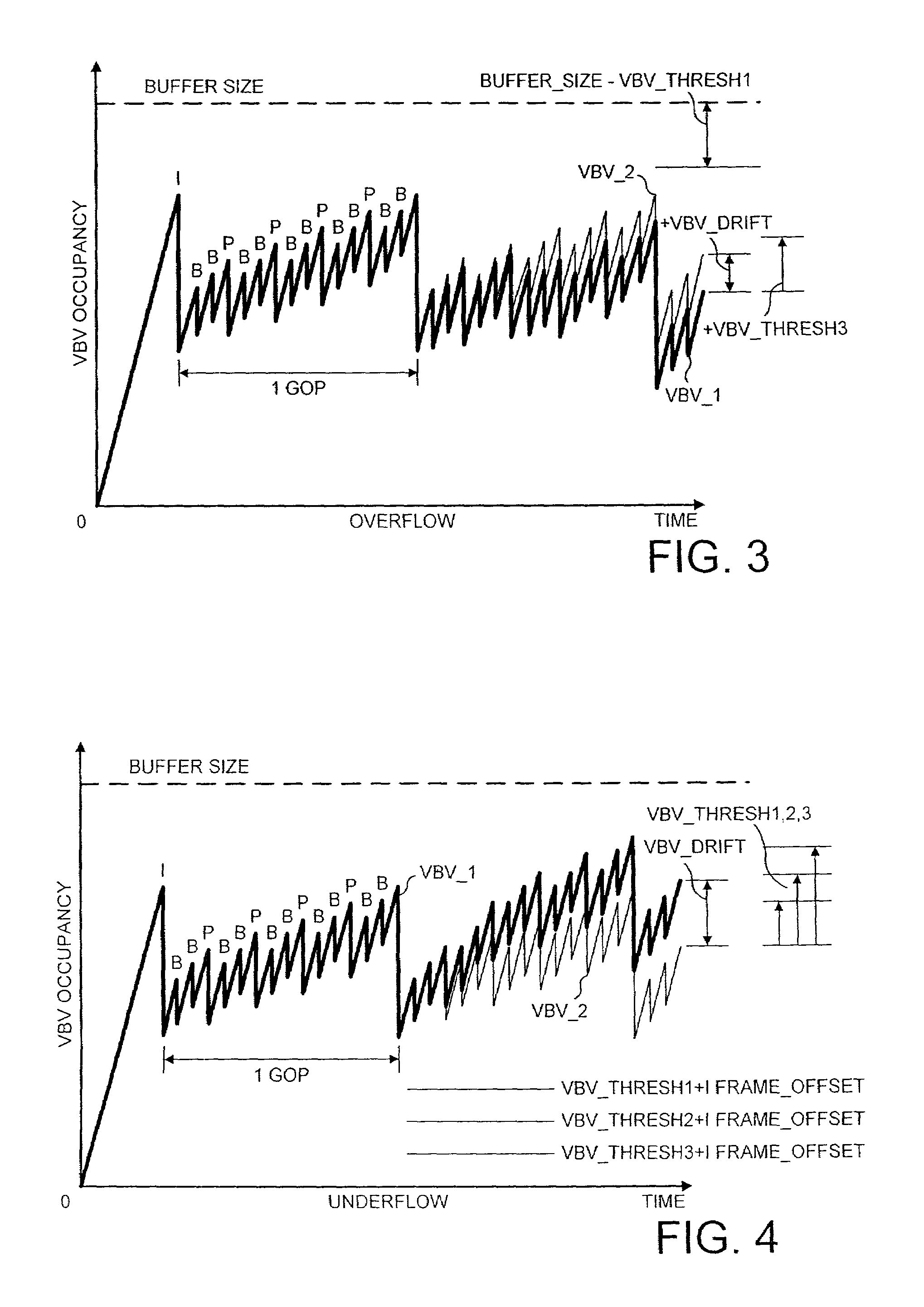
[0027]Thus the invention avoids underflow whilst preserving image quality by reusing preserved parameters and maintaining a high bit rate when the tendency towards underflow is low, and reduces the reuse of the preserved parameters and reduces the bit rate as the tendency towards underflow increases. Preferably, the values of V—1 and V—2 are controlled so that they converge by controlling the bit rate.
[0041]Thus the invention reduces overflow of the downstream buffer whilst preserving image quality by reusing the preserved parameters and adding stuffing bits.

Problems solved by technology

Decoding and reencoding tends to reduce image quality.
This can cause the buffer of a downstream decoder to underflow or overflow.

Method used


Image

  • Signal processing
  • Signal processing
  • Signal processing

Examples


Embodiment Construction

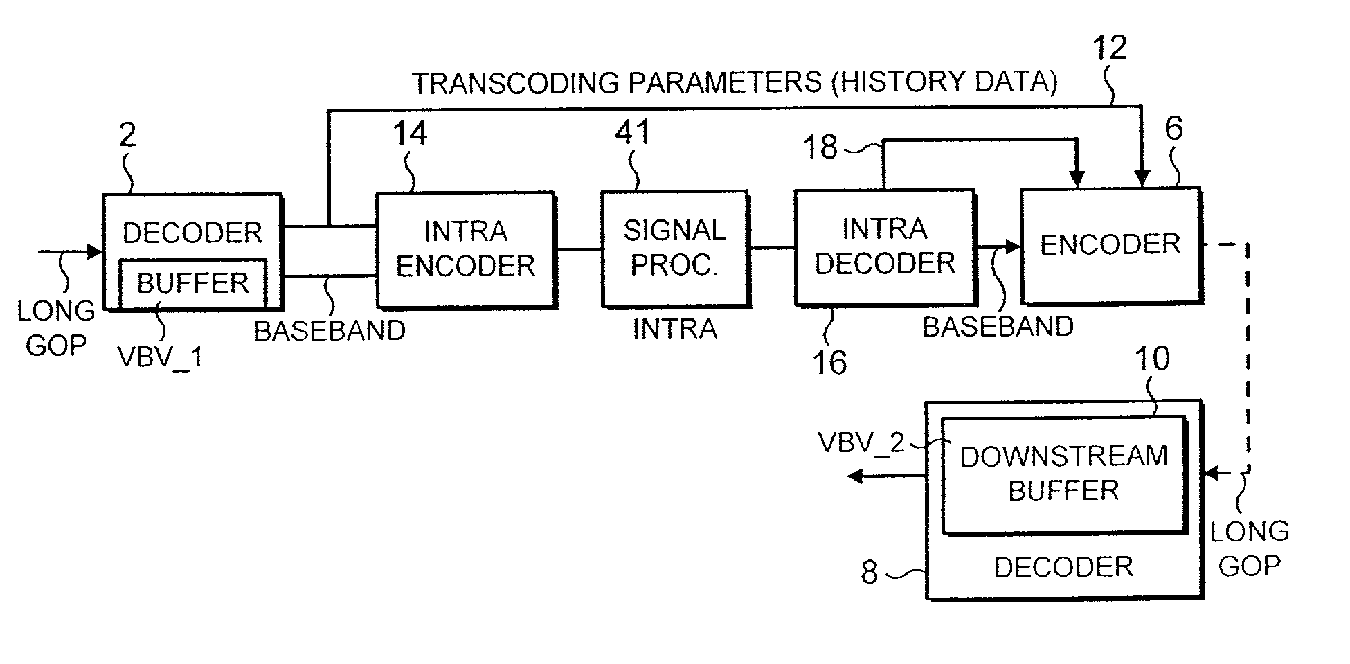
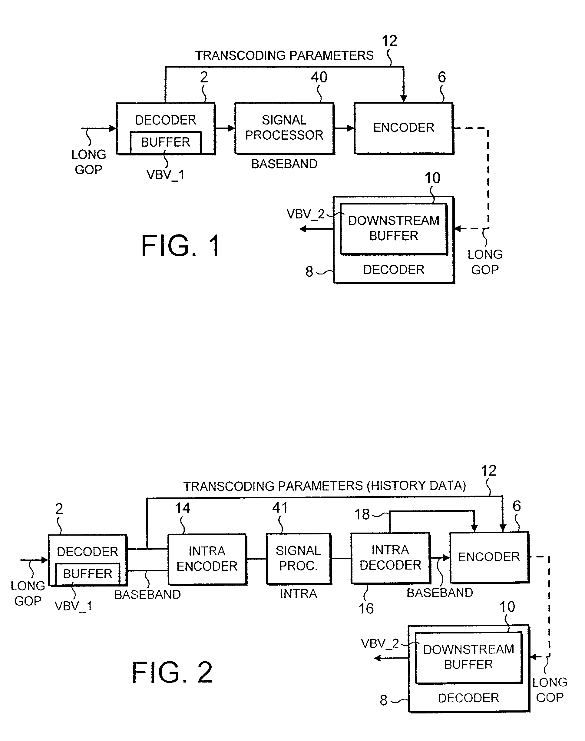
[0052]The illustrative system of FIG. 1 comprises a decoder 2 which receives a digital video bitstream compressed according to the MPEG 2 standard. The bitstream comprises a “long GOP” of frames, for example IBBPBBPBBPBB. The decoder 2 decompresses the compressed video to digital baseband. The compression parameters of the I, P and B frames are preserved for transfer to an encoder 6 as indicated by line 12. The parameters include for all frames (i.e. I, P and B):[0053]Identification of the frame type, I P and B;[0054]Quantiser scale;[0055]DCT type ( field or frame); and[0056]Quantiser matrix.

[0057]The parameters additionally include for predicted frames (i.e. P and B frames):[0058]Prediction type (field or frame);[0059]Macroblock mode; and[0060]Motion vectors.

[0061]The decompressed baseband video is applied to a signal processor 40. The processor 40 may be, inter alia: simply a communications channel for transferring the decompressed video to the encoder 6; a store for storing the b...


PUM


Abstract

A decoder 2 decodes a first compressed digital video bitstream whilst preserving the compression parameters thereof, the compression parameters including a first buffer occupancy value VBV—1 representing the occupancy by the said first bitstream of a buffer of the decoder. A signal processor 40 processes the decompressed bitstream. An encoder 6 compresses the processed bitstream to produce a second compressed bitstream having a target bit rate, optionally with reuse of the said compression parameters of the first bitstream, the second bitstream having a second occupancy value VBV—2 representing the occupancy of a downstream decoder buffer by the said second bitstream. The encoder controls (i) the target bit rate of the second bitstream and (ii) the recoding of the second bitstream to meet the said target bit rate, the target bit rate being varied in dependence on one or both of (a) VBV—2 and (b) the difference between VBV—1 and VBV—2, and the degree of reuse of the said preserved parameters being varied in dependence on one or both of (a) the degree to which VBV—2 tends towards underflow and (b) the degree to which VBV—1 differs from VBV—2 tending towards underflow.In addition, stuffing bits are added to the bitstream if VBV—2 is tending towards overflow of the downstream buffer and / or VBV—2 differs from VBV—1 tending towards overflow.

Description

BACKGROUND OF THE INVENTION[0001]1. Field of the Invention[0002]The present invention relates to a signal processing system, a method of signal processing and a computer program product arranged to implement the method. Embodiments of the invention relate to processing compressed video bit streams. Preferred embodiments relate to processing video bit streams compressed according to the MPEG 2 standard.[0003]2. Description of the Prior Art[0004]The invention and its background will be discussed by way of example with reference to MPEG-2 video bitstreams. However the invention is not limited to MPEG-2.[0005]MPEG-2 is well known from for example ISO / IEC / 13818-2, and will not be described in detail herein. MPEG-2 compressed video comprises groups of I, P and / or B frames known as GOPs, Groups of Pictures. I, P and B frames are well known. An I or Intra-encoded frame contains all the information of the frame independently of any other frame. A P frame in a GOP ultimately depends on an I f...

Claims


Application Information

Patent Timeline
IPC IPC(8): H04N7/12H04N5/765H04N5/91H04N7/24H04N7/26H04N7/50
CPCH04N21/23424H04N21/44016H04N19/46H04N19/15H04N19/40H04N19/107H04N19/152H04N19/177H04N19/61
Inventor SAUNDERS, NICHOLAS IANPORTER, ROBERT MARK STEFAN
Owner SONY UK LTD
Learn More