Transmission apparatus, reception apparatus and digital radio communication method

a technology of digital radio communication and transmission apparatus, applied in the direction of pulse technique, phase-modulated carrier system, modulation, etc., can solve the problems of deteriorating data quality, reducing error resiliency features during data demodulation, and uneven fluctuations in the transmission path. achieve the effect of improving data transmission efficiency and data quality

Inactive Publication Date: 2006-01-31
REDWOOD TECHNOLOGIES LLC
View PDF10 Cites 74 Cited by
  • Summary
  • Abstract
  • Description
  • Claims
  • Application Information

AI Technical Summary

Benefits of technology

[0007]It is an object of the present invention to provide a transmission apparatus, a reception apparatus and a digital radio communication method that improve data transmission efficiency and data quality.

Problems solved by technology

Here, in the case of a radio communication, fluctuations in the transmission path occur due to fading and in terrestrial mobile communication in particular, fluctuations in the transmission path are not uniform.
Therefore, when fluctuations in the transmission path are intense or the level of the reception signal of the receiver is small, error resiliency features during data demodulation reduces and the quality of data deteriorates.
On the other hand, when fluctuations in the transmission path are gentle or the level of the reception signal on the receiving side is large, the data transmission efficiency cannot be improved regardless of data quality.

Method used


Image

  • Transmission apparatus, reception apparatus and digital radio communication method
  • Transmission apparatus, reception apparatus and digital radio communication method
  • Transmission apparatus, reception apparatus and digital radio communication method

Examples


embodiment 1

[0036]Embodiment 1 describes a digital radio communication method by which the interval for inserting known pilot symbols and the modulation system of information symbol are changed according to the communication situation.

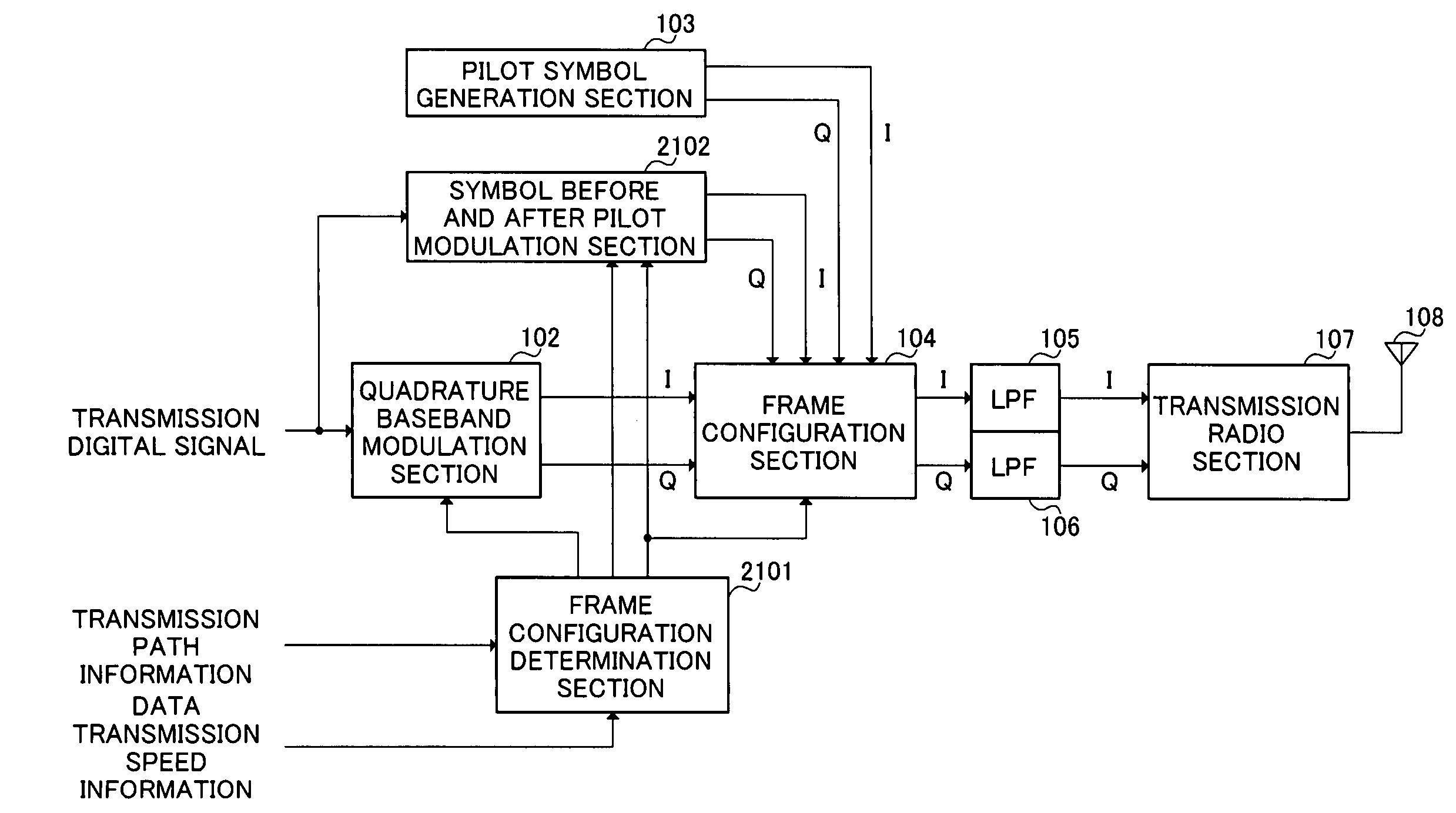
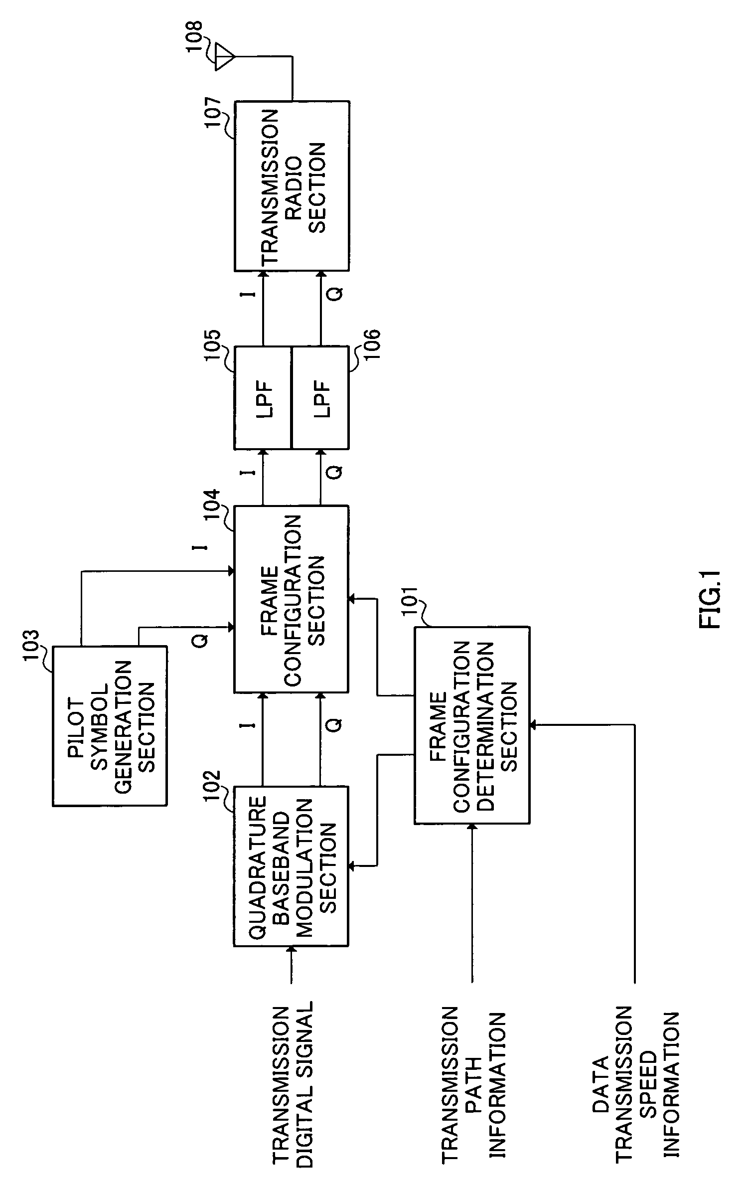
[0037]FIG. 1 is a block diagram showing a configuration of a transmission apparatus according to this embodiment. As shown in FIG. 1, the transmission apparatus according to this embodiment mainly consists of frame configuration determination section 101, quadrature baseband modulation section 102, pilot symbol generation section 103, frame configuration section 104, and LPFs (Low Pass Filters) 105 and 106, transmission radio section 107 and transmission antenna 108.

[0038]Frame configuration determination section 101 judges the communication situation based on transmission path information that indicates the degree of fluctuations of the transmission path due to fading and based on data transmission speed information that indicates the transmission speed of transm...

embodiment 2

[0058]Embodiment 2 describes a digital radio communication method by which the interval for inserting BPSK modulation symbol and the modulation system of information symbol other than the above BPSK modulation symbol are changed according to the communication situation.

[0059]FIG. 6 is a block diagram showing a configuration of the transmission apparatus according to this Embodiment. Here, in the transmission apparatus shown in FIG. 6, the components common to those in the transmission apparatus shown in FIG. 1 are assigned the same reference numerals as those in FIG. 1 and their explanations will be omitted.

[0060]In the transmission apparatus in FIG. 6, frame configuration determination section 601 differs in the way of operation from the frame configuration determination section 101 in FIG. 1. Also, when compared to FIG. 1, the transmission apparatus in FIG. 6 adopts the configuration with BPSK symbol modulation section 602, instead of pilot symbol generation section 103, added.

[00...

embodiment 3

[0074]Embodiment 3 describes a digital radio communication method by which the interval for inserting QPSK modulation symbols and the modulation system of information symbol other than the above QPSK modulation symbols are changed according to the communication situation.

[0075]FIG. 11 is a block diagram showing a configuration of the transmission apparatus according to this Embodiment. In the transmission apparatus shown in FIG. 11, the components common to those in the transmission apparatus shown in FIG. 1 are assigned the same reference numerals as those in FIG. 1 and their explanations will be omitted.

[0076]In the transmission apparatus in FIG. 11, frame configuration determination section 1101 differs in the way of operation from the frame configuration determination section 101 in FIG. 1. Also, when compared to FIG. 1, the transmission apparatus in FIG. 11 adopts a configuration having QPSK symbol modulation section 1102 instead of pilot symbol generation section 103.

[0077]Fra...


PUM


Abstract

Frame configuration determination section 101 judges a communication situation based on the transmission path information indicating the level of fluctuations of the transmission path due to fading and data transmission speed information indicating the transmission speed of the transmission data based on the level of the reception signal and determines the interval of inserting a known pilot symbol and the modulation system of a transmission digital signal. Quadrature baseband modulation section 102 modulates the transmission digital signal to a quadrature baseband signal according to the modulation system indicated from frame configuration determination section 101. Pilot symbol generation section 103 generates a pilot symbol known between the transmitting and receiving sides. Frame configuration section 104 inserts the known pilot symbol output from pilot symbol generation section 103 at the insertion interval instructed from frame configuration determination section 101 to configure a frame. This makes it possible to flexibly improve the data transmission efficiency and the quality of data at the same time.

Description

BACKGROUND OF THE INVENTION[0001]1. Field of the Invention[0002]The present invention relates to a transmission apparatus, a reception apparatus and a digital radio communication method for digital radio communications.[0003]2. Description of the Related Art[0004]As a conventional digital modulation system, a technology described in Unexamined Japanese Patent Publication No. HEI 1-196924 is known. This is the technology whereby the transmitting side configures a frame by inserting one known pilot symbol per N data symbols and whereby the receiving side estimates a frequency offset and amount of amplitude distortion by using the pilot symbol and removes these frequency offset and amplitude distortion for demodulation.[0005]Here, in the case of a radio communication, fluctuations in the transmission path occur due to fading and in terrestrial mobile communication in particular, fluctuations in the transmission path are not uniform. When fluctuations in the transmission path are intens...

Claims


Application Information

Patent Timeline
Patent Type & Authority Patents(United States)
IPC IPC(8): H04L27/36H04L23/02H04L1/00H04L27/34H04L27/18H04L27/20H04L27/22
CPCH04L1/0003H04L1/0006H04L27/12H04L27/34H04L27/3455H04L27/206H04B1/38
Inventor MURAKAMI, YUTAKATAKABAYASHI, SHINICHIROORIHASHI, MASAYUKIMATSUOKA, AKIHIKO
Owner REDWOOD TECHNOLOGIES LLC
Why Eureka
Try Eureka