BS digital broadcasting receiver

a digital broadcasting receiver and receiver technology, applied in the direction of synchronisation signal speed/phase control, television system, phase-modulated carrier system, etc., can solve the problem of little fixed deterioration of reception, the factor of hysteresis occurrence is dependent, and the effect of impossible to predi

Inactive Publication Date: 2006-01-31
RAKUTEN INC
View PDF8 Cites 9 Cited by
  • Summary
  • Abstract
  • Description
  • Claims
  • Application Information

AI Technical Summary

Problems solved by technology

However, there has been a problem that, in the case where performance of a down converter of an outdoor unit (ODU) or the like including an antenna is insufficient, reception with little fixed deterioration is difficult when performing the burst reception compared with the continuous reception due to influence of its phase noise.
Thus, there is hysteresis between mutual switching points of the continuous reception and the burst reception (shown by an arrow (c) in FIG. 13 for instance), and there further arises a problem that a factor of this hysteresis occurrence depends on the phase noise of the ODU.
If phase noise characteristics of the ODU are known in advance, technical countermeasures can be taken, whereas it is actually impossible to predict the characteristics since the ODUs purchased by users are various.
In order to solve this, it is also thinkable to detect a degree of the ODU phase noise, which is by no means easy.
Thus, there is hysteresis between mutual switching points of the continuous reception and the burst reception (shown by an arrow (f) in FIG. 13 for instance), and there further arises the same problem that the factor of this hysteresis occurrence depends on the phase noise of the ODU.

Method used


Image

  • BS digital broadcasting receiver
  • BS digital broadcasting receiver
  • BS digital broadcasting receiver

Examples


Embodiment Construction

[0040]Hereafter, a BS digital broadcasting receiver related to the present invention will be described by an embodiment thereof.

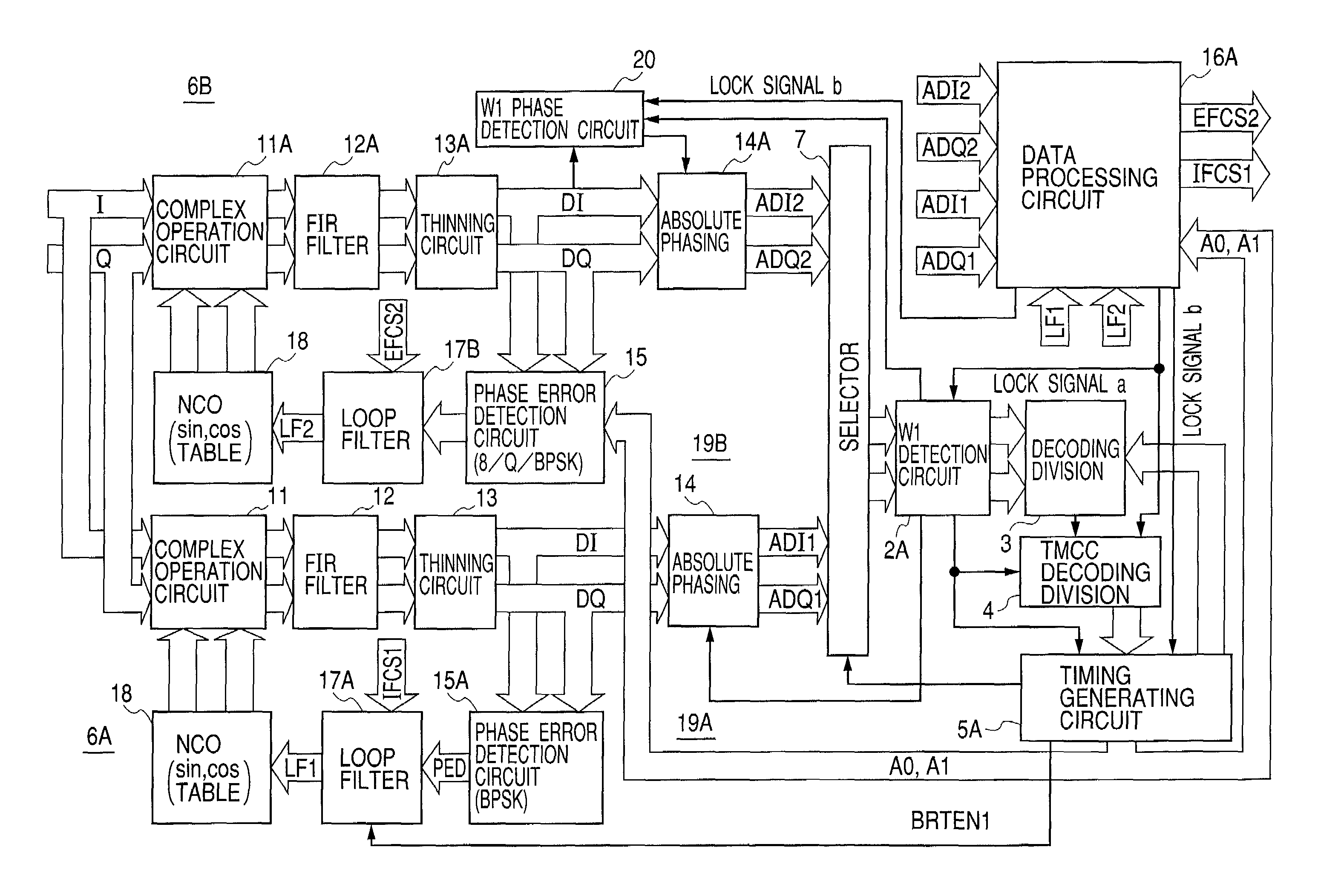
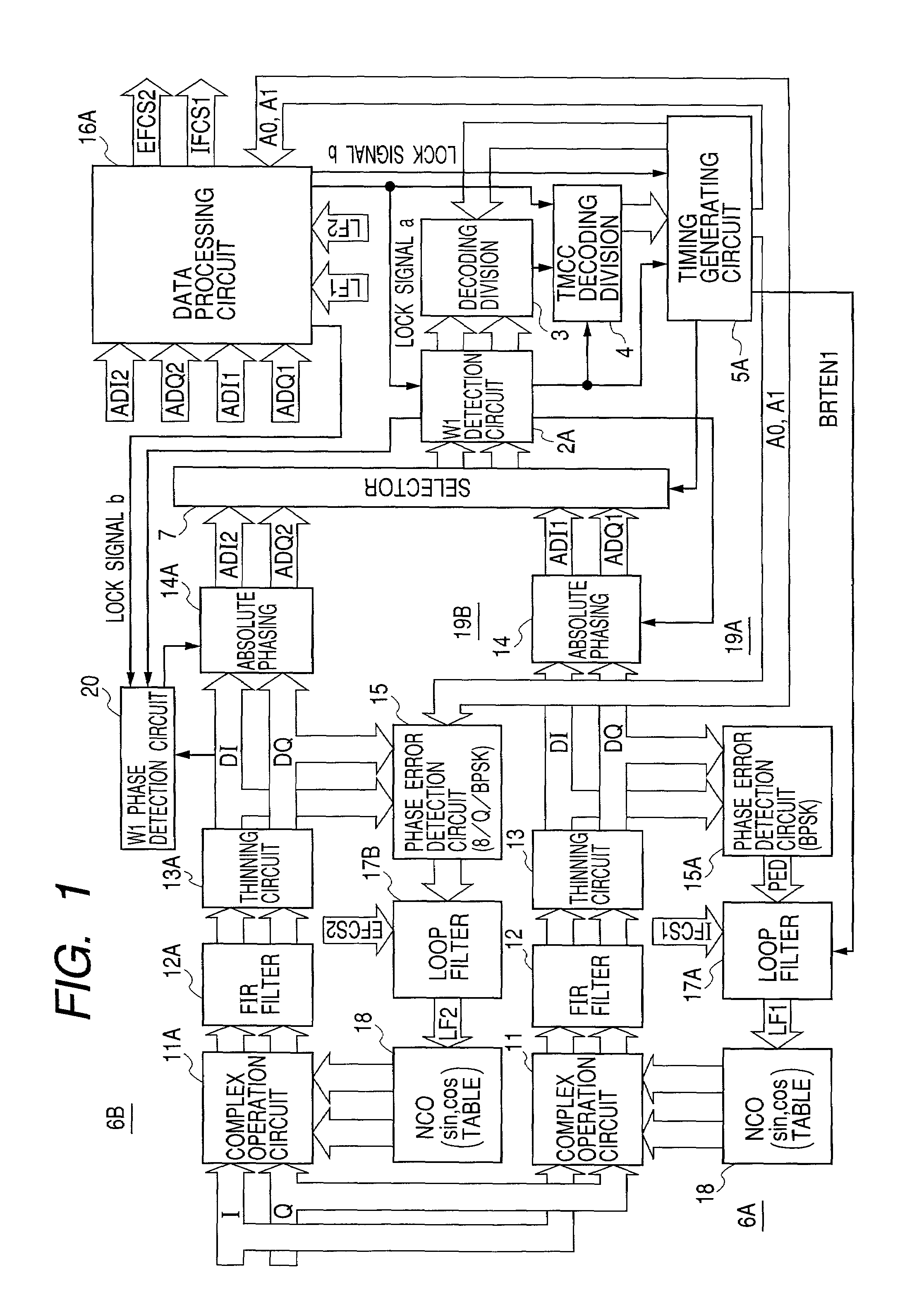
[0041]FIG. 1 is a block diagram showing a configuration of a BS digital broadcasting receiver related to an embodiment of the present invention. The BS digital broadcasting receiver related to an embodiment of the present invention has two demodulator circuits. In addition, FIG. 1 shows the same symbols as to the same components as those of a conventional BS digital broadcasting receiver shown in FIG. 12.

[0042]The BS digital broadcasting receiver related to an embodiment of the present invention has demodulator circuits 6A and 6B. The demodulator circuit 6A has a phase error detection circuit 15A having a phase error table for detecting a phase error signal only from demodulation data of a BPSK modulation wave (also referred to as the demodulation data of a BPSK modulation section, and likewise in the case of other modulation) instead of a phase error detec...


PUM


Abstract

A BS digital broadcasting receiver which eliminates the uncertainty of an ODU's phase noise-dependent switching point when switching a receiving system. The receiver is provided with a demodulator circuit (6A) having a carrier regenerating circuit (19A) based on demodulation data in a BPSK modulation section, and with a demodulator circuit (6B) having a carrier regenerating circuit (19B) based on demodulation data in each time-division modulation section, wherein, when a lock for carriers regenerated by the carrier regenerating circuit (19A) is maintained and carriers regenerated by the carrier regenerating circuit (19B) is locked, demodulation data, in the BPSK demodulation section and a QPSK demodulation section, output from the demodulator circuit (6A) and 8-PSK-modulated demodulation data output from the demodulator circuit (6B) are selected by a selector (7) for outputting.

Description

TECHNICAL FIELD[0001]The present invention relates to a BS digital broadcasting receiver for receiving a BS digital signal wherein a signal modulated by a hierarchical transmission system typically represented by a BS digital broadcasting receiver for receiving a BS digital TV broadcasting is time-division-multiplexed.BACKGROUND ART[0002]A BS digital broadcasting adopts a hierarchical modulation system and a system called burst symbol insertion that allows reception at a low CNR. A main signal is sent by frame and through time division multiplexing by using one or more modulation systems of 8PSK modulation, QPSK modulation and BPSK modulation. A burst symbol (BS) and a TMCC signal are BPSK-modulated.[0003]As publicly known, one frame in the hierarchical transmission system is comprised of 39,936 symbols by inserting burst symbols (BS) among the TMCC signals, 8PSK main signals, . . . , QPSK main signals and the main signals as shown in FIG. 11A.[0004]As shown in FIG. 12, a BS digital...

Claims


Application Information

Patent Timeline
Patent Type & Authority Patents(United States)
IPC IPC(8): H03D3/22H04L27/22H04J3/00H04L1/00H04L7/08H04L27/00H04L27/227H04L27/233H04L27/32H04N5/44H04N5/455H04N7/20
CPCH04L27/22H04L27/2272H04N5/455H04L2027/003H04L2027/0057H04L2027/0079H04L2027/0095H04N5/4401H04L2027/0073H04N21/426H04N21/4382H04N21/6143
Inventor SHIRAISHI, KENICHIHORII, AKIHIROMATSUDA, SHOJI
Owner RAKUTEN INC
Why Eureka
Try Eureka