Facility monitoring method

a technology of monitoring method and monitoring method, which is applied in the direction of testing/monitoring control system, instruments, nuclear elements, etc., can solve the problem of not providing an operator with an instantaneous view of the overall performance of the plant, and achieve the effect of reducing the performance factor of electrical power consumption, and improving the overall performance factor

Active Publication Date: 2006-01-31
PRAXAIR TECH INC
View PDF11 Cites 83 Cited by
  • Summary
  • Abstract
  • Description
  • Claims
  • Application Information

AI Technical Summary

Benefits of technology

[0008]In accordance with the present invention, current values including a rate of usage of the at least one commodity, a production rate of the at least one product and a unit production cost are monitored. The unit production cost is computed by dividing at least a cost value referable to the rate of usage of at least one commodity by the production rate of the at least one product. Running averages of the rate of usage of the at least one commodity and the unit production cost are computed over a predetermined time interval and stored. Base values are determined. The base values relate to steady state operation of the facility for each of the running averages.

Problems solved by technology

This type of monitoring, while important, does not provide an operator of an instantaneous view of the overall performance of the plant.

Method used


Image

  • Facility monitoring method
  • Facility monitoring method
  • Facility monitoring method

Examples


Embodiment Construction

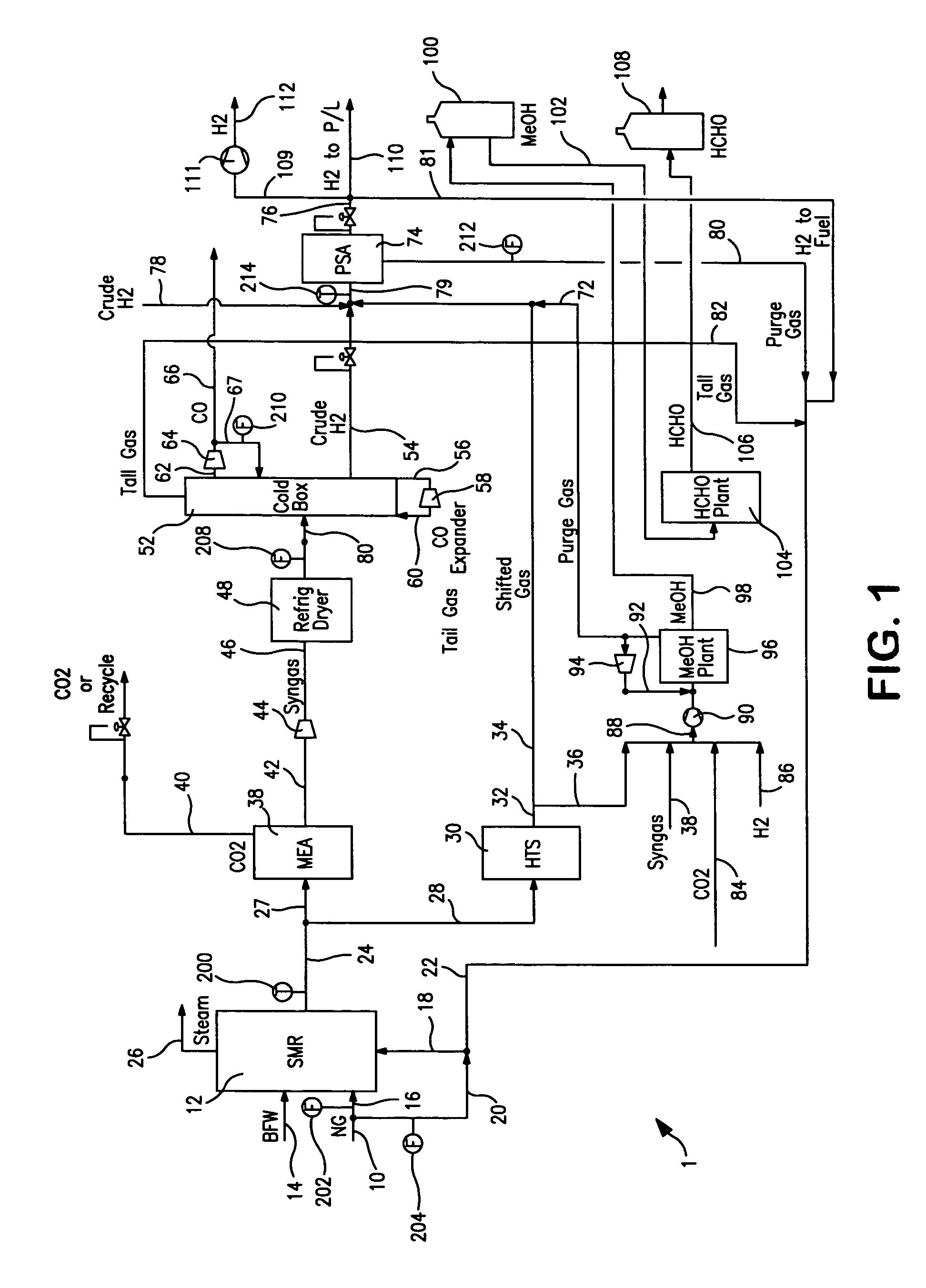
[0021]With reference to FIG. 1, a process flow diagram is illustrated of a facility containing a plant 1 that is designed to produce hydrogen and carbon monoxide products. Carbon dioxide, methanol and formaldehyde products are also produced. Plant 1 is one of two plants located within the facility. It is understood, however, that as mentioned above the application of the present invention is not limited to any particular type of plant and facility and has more general application.

[0022]Plant 1 consists of a series of unit operations that begins with the steam methane reforming of a natural gas stream 10 (“NG”) within a conventional steam methane reformer 12 (“SMR”). The steam is conventionally created in a known manner within a convective section of steam methane reformer 12 from a boiler feed water stream 14 (“BFW”). Although not illustrated, steam can also be produced from heat recovery steam generators of the type that would be used in cooling streams, for example, a synthesis ga...


PUM


Abstract

A method of monitoring plant performance within a facility in which having averages of cost contributing items such as raw material usage, product recovery, unit production efficiency, power usage and controller error performance are evaluated, statistically weighted to determine an overall performance factor. The overall performance factor applies an instantaneous indication of plant operation. Excursions of individual performance factors diagnose plant problems.

Description

FIELD OF THE INVENTION[0001]A method of monitoring the performance of a facility in which individual performance factors related to raw material usage, product recovery, the percentage of product recovered, production efficiency and controller tuning are individually monitored as well as an overall plant performance factor that is made up of the individual performance factors.BACKGROUND OF THE INVENTION[0002]There exists a variety of facilities to process raw materials in one or more unit operations to produce one or more products.[0003]For instance, in a hydrogen-carbon monoxide plant, natural gas is used both as a reactant feed along with steam to a steam methane reformer and as a fuel for burners that support the endothermic steam methane reforming reaction. Steam methane reforming produces a synthesis gas product that contains carbon monoxide, carbon dioxide and hydrogen. In subsequent operations, the synthesis gas is processed by an amine scrubbing unit to remove carbon dioxide...

Claims


Application Information

Patent Timeline
Patent Type & Authority Patents(United States)
IPC IPC(8): G06F19/00
CPCG05B23/0294
Inventor DADEBO, SOLOMON A.KATENDE, EDWARDKLEIN, III, FRANK J.
Owner PRAXAIR TECH INC
Why Eureka
Try Eureka