Horizontal axis wind turbine and method for measuring upflow angle

a wind turbine and horizontal axis technology, applied in the direction of machines/engines, golf clubs, instruments, etc., can solve the problems of lack of reliability, 3-d ultrasonic anemometers, high cost and large volume, and achieve the effects of improving reliability, low cost, and improving the predictability of electricity production

Active Publication Date: 2006-02-07
HITACHI LTD
View PDF4 Cites 12 Cited by
  • Summary
  • Abstract
  • Description
  • Claims
  • Application Information

AI Technical Summary

Benefits of technology

[0008]An object of the present invention is to improve predictability of the production of electricity by achieving measurement of the “upflow angle” of the wind against a rotor of a horizontal axis wind turbine at low cost and with high reliability.
[0015]It is possible to measure the upflow angle by means of an upflow angle measuring section based on the difference (or the ratio) obtained from the wind speeds measured by the first anemometer and the second anemometer by use of the relationship. Consequently the upflow angle can be continuously measured at low cost with high reliability without using an expensive device. Furthermore because of adoption of two anemometers, when either anemometer breaks down, the other anemometer makes measurement of wind speed for control possible. In addition to ensuring redundancy of an anemometer and shortening the stopping time of a wind turbine, a loss of power production in the down time can be reduced.
[0062]According to the present invention, because of providing the two anemometers (the first anemometer and the second anemometer) disposed above and below the level of the horizontal plate, the upflow angle can be measured at low cost with high reliability based on the wind speed difference or the wind speed ratio obtained from the wind speeds measured by the two anemometers, and thus it is possible to contribute to improvement of predictability of the production of electricity.

Problems solved by technology

Wind-generated electricity systems are often installed in complex topography.
The above-described 3-D ultrasonic anemometers, however, have a problem that it is expensive and large.
Therefore they have reservations about durability and lack reliability.

Method used


Image

  • Horizontal axis wind turbine and method for measuring upflow angle
  • Horizontal axis wind turbine and method for measuring upflow angle
  • Horizontal axis wind turbine and method for measuring upflow angle

Examples


Embodiment Construction

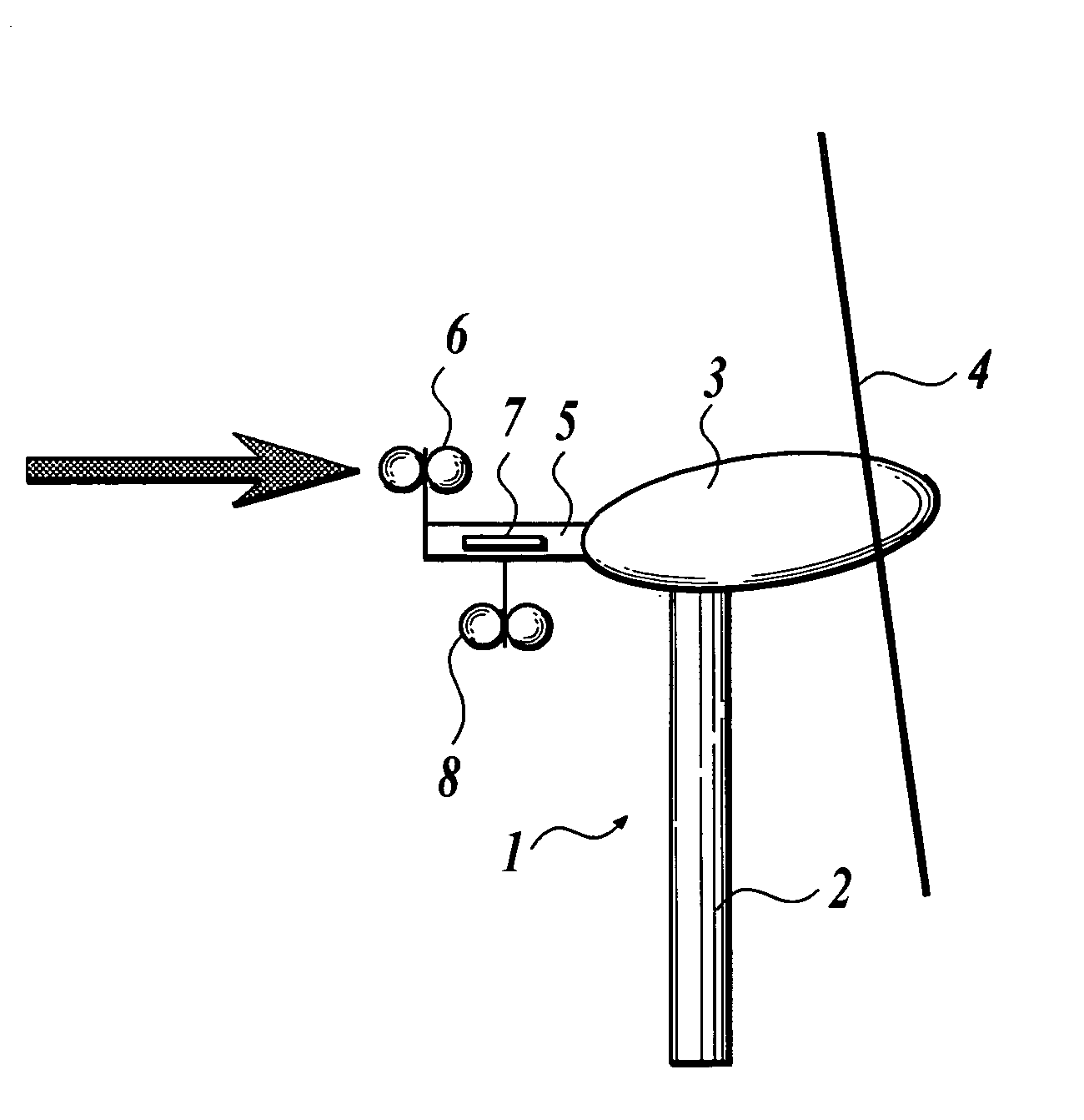
[0069]Hereinbelow an embodiment of the present invention will be described in detail with drawings. In the present embodiment, a downwind horizontal axis wind turbine 1 shown in FIG. 1 is adopted as an example of a horizontal axis wind turbine.

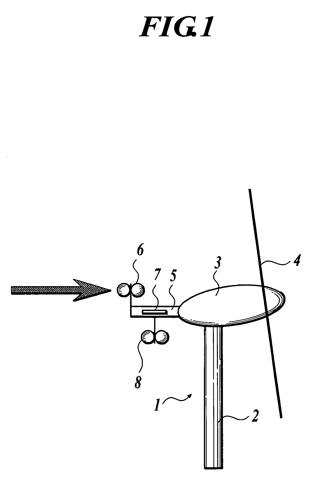
[0070]The configuration of the horizontal axis wind turbine according to the present embodiment will be described. The horizontal axis wind turbine 1 comprises, as shown in FIGS. 1 and 2, a tower 2, a nacelle 3 attached on the top of the tower 2, a main shaft (not shown) extending in a substantially horizontal direction and pivotally supported on the nacelle 3, a rotor 4 attached on the main shaft, a boom 5 set up so as to protrude at a predetermined distance on the upwind side of the nacelle 3, a first anemometer 6 attached to the upper side of the peripheral part of the upwind side of the boom 5 in such a way that its rotating shaft is in a substantially vertical direction, a horizontal plate 7 set up on a substantially central portion in th...


PUM


Abstract

A horizontal axis wind turbine includes: a horizontal plate disposed on upwind side of a rotational central portion of a rotor; a first anemometer disposed at an upper position of upwind side of the horizontal plate; a second anemometer disposed at a lower position of the horizontal plate; and an upflow angle measuring section for measuring an upflow angle based on a wind speed difference or a wind speed ratio obtained from wind speeds measured by the first anemometer and the second anemometer.

Description

BACKGROUND OF THE INVENTION[0001]1. Field of the Invention[0002]The present invention relates to a horizontal axis wind turbine and a method for measuring an upflow angle.[0003]2. Description of Related Art[0004]In recent years, horizontal axis wind turbines have been in practical use in order to gain electric power from natural wind. The performance of the horizontal axis wind turbines is shown by a power curve representing relationship between the wind speed at hub (the wind speed at the rotational central portion of a rotor of a horizontal axis wind turbine) and power (production of electricity) in general. The production of electricity leading directly to profitability is predicted based on the power curve and the wind speed at hub estimated by simulation or observed in advance.[0005]Wind-generated electricity systems are often installed in complex topography. In such topography, the wind speed varies with not only the height from ground but also the horizontal position, and in ...

Claims


Application Information

Patent Timeline
Patent Type & Authority Patents(United States)
IPC IPC(8): G01W1/00G01P13/00F03D1/06F03D11/00F03D11/04G01P5/06G01P13/02
CPCF03D11/00G01P13/02G01P5/06F05B2260/80F05B2260/845Y02E10/726Y02E10/721Y02E10/722F05B2270/32F05B2270/321F03D17/00Y02E10/72
Inventor YOSHIDA, SHIGEO
Owner HITACHI LTD
Why Eureka
Try Eureka