Fuel injector

a fuel injector and fuel technology, applied in the direction of fuel injection apparatus, wear-reducing fuel injection, charge feed system, etc., can solve the problems of complex production and installation of sock-shaped filter elements, high cost, easy twisting and shifting, etc., and achieve excellent fit and shorten the length of the fuel injector.

Inactive Publication Date: 2006-02-07
ROBERT BOSCH GMBH
View PDF9 Cites 12 Cited by
  • Summary
  • Abstract
  • Description
  • Claims
  • Application Information

AI Technical Summary

Benefits of technology

[0004]In contrast, the fuel injector of the present invention has the advantage over the related art that, in addition to a filter element positioned in the fuel feed, an additional filter element is provided which is located downstream from the armature. It allows either a second, finer filtering of the fuel flowing through in addition to the filtering by the first filter element, or replacing the first filter element, which has the advantage of allowing a shorter length for the fuel injector.
[0005]It is believed that it is advantageous in this context that the second filter element is able to be produced in a simple manner from a screen mesh or by introducing orifices into an annular sheet metal. The opening may be produced in a variety of ways, such as laser drilling, etching, eroding or stamping.
[0006]It is believed that it is also advantageous that the filter element may either be loosely placed into the sleeve positioned downstream from the armature, or be braced against it or welded to it, thereby holding the filter element in place.
[0007]An advantageous, additional arrangement for fixation is offered by a concave, convex or dish-like form of the filter element, since in this case a fixation is possible by axial bracing between the armature and the sleeve, which may be biased relative to one another for damping purposes, without requiring additional fixation measures, yet providing excellent accuracy of fit.

Problems solved by technology

The fuel injector discussed in DE 44 21 881 A1 is such that the production and installation of a sock-shaped filter element may be complex and, thus, cost-intensive.
Because of the large surface of the filter element, it is susceptible to twisting and shifting during the operation of the fuel injector, due to considerable valve-needle movement.

Method used


Image

  • Fuel injector
  • Fuel injector
  • Fuel injector

Examples


Embodiment Construction

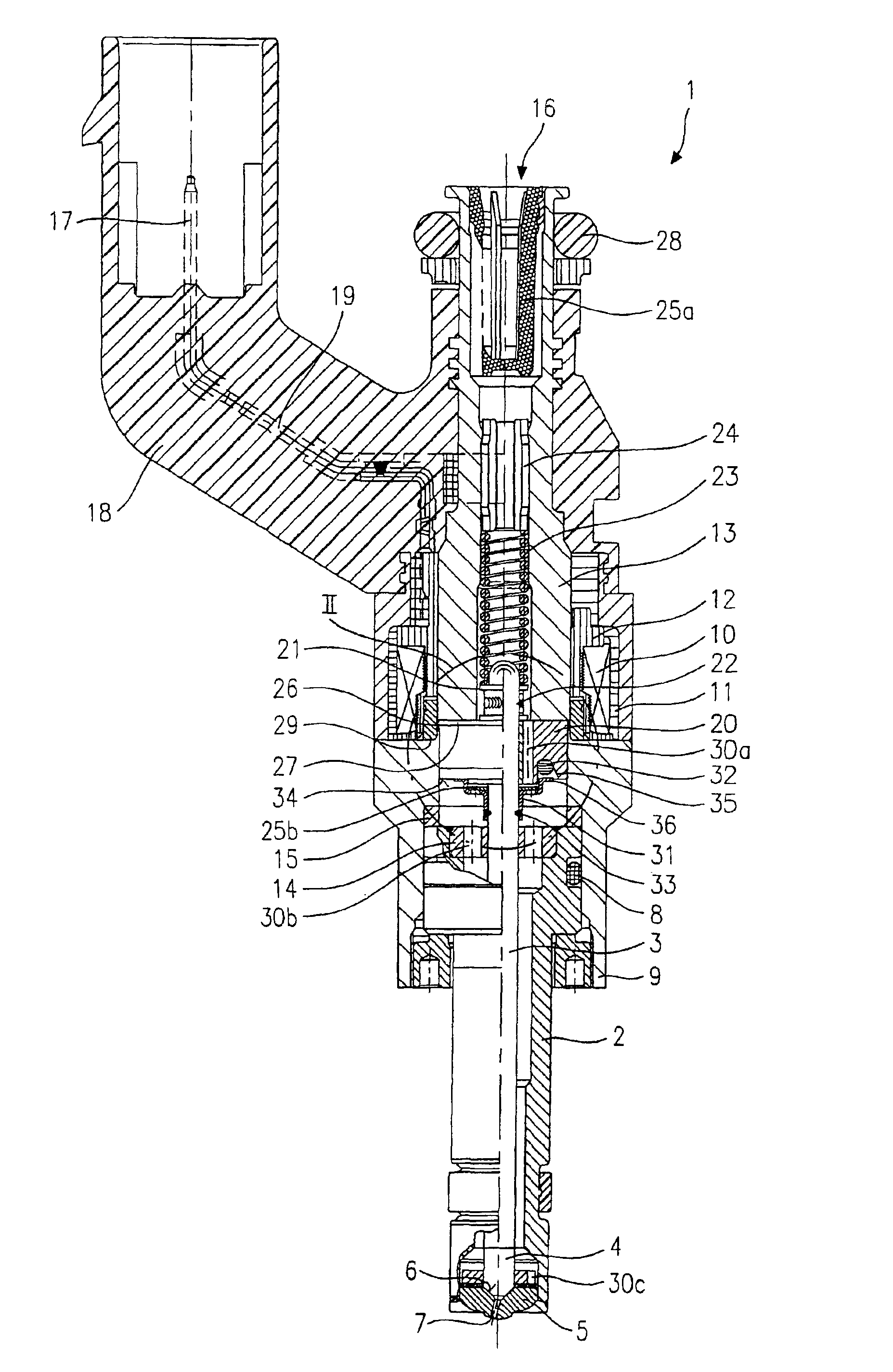
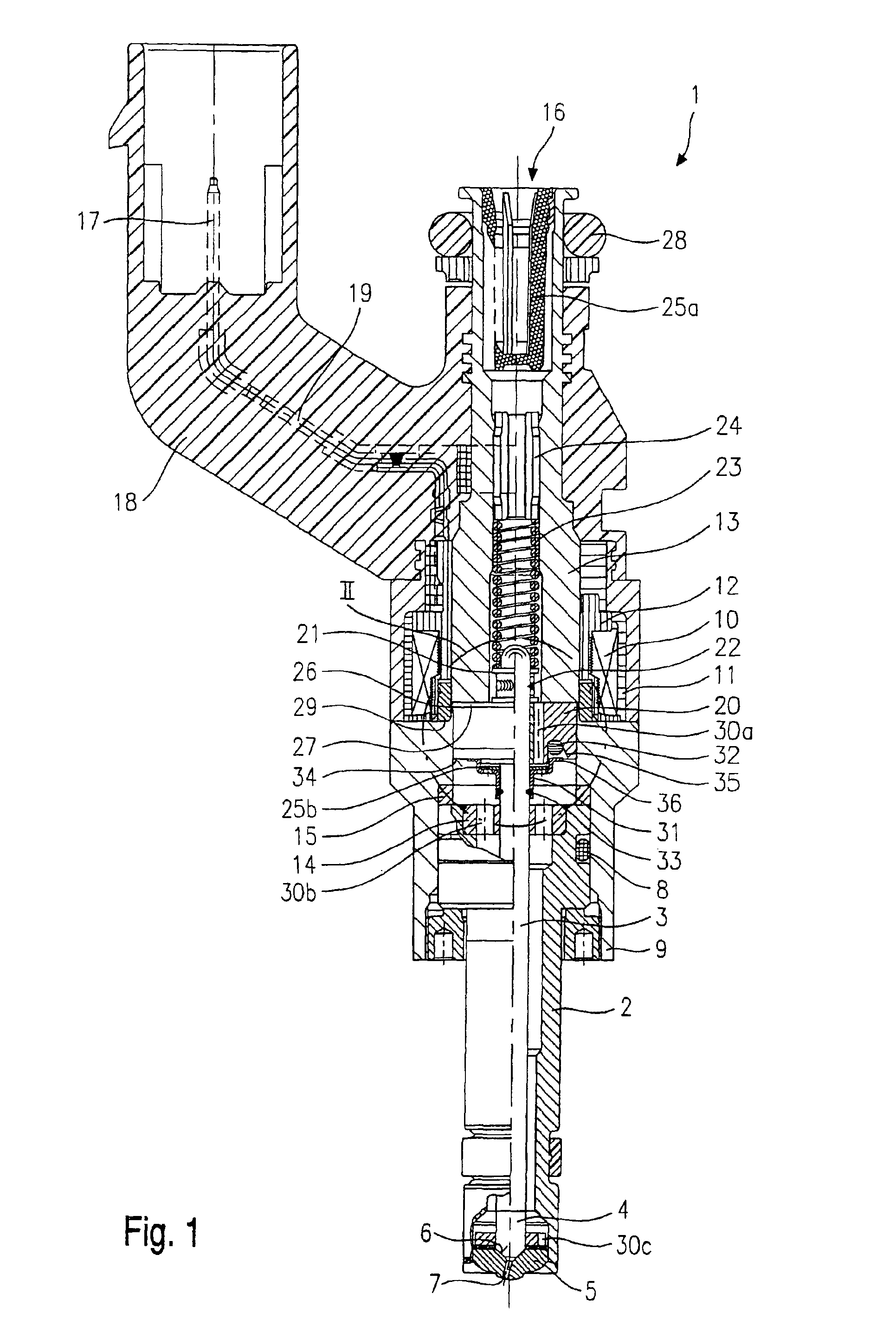
[0010]A fuel injector 1, shown in FIG. 1, is designed in the form of a fuel injector for fuel-injection systems of mixture-compressing internal combustion engines having externally supplied ignition. Fuel injector 1 is particularly suited for the direct injection of fuel into a combustion chamber (not shown) of an internal combustion engine.

[0011]Fuel injector 1 includes a nozzle body 2 in which a valve needle 3 is positioned. Valve needle 3 is in operative connection with a valve-closure member 4, which cooperates with a valve-seat surface 6 situated on a valve-seat member 5 to form a sealing seat. In the exemplary embodiment, fuel injector 1 is an inwardly opening fuel injector 1, which has one spray-discharge orifice 7. Seal 8 seals nozzle body 2 from an outer pole 9 of a magnetic coil 10. Magnetic coil 10 is encapsulated in a coil housing 11 and wound on a coil brace 12, which rests against an inner pole 13 of magnetic coil 10. Inner pole 13 and outer pole 9 are separated from e...


PUM


Abstract

A fuel injector for fuel-injection systems of internal combustion engines includes a valve needle cooperating with a valve-seat surface to form a sealing seat, and an armature engaging with the valve needle, the armature being axially moveable at the valve needle and being damped, via a damping element, which is located in a recess in a downstream-side end face of the armature, with respect to a cup-shaped sleeve positioned downstream from the armature and joined to the valve needle in force-locking manner. Furthermore, the fuel injector includes a filter element, the filter element being positioned downstream from the armature in the cup-shaped sleeve.

Description

FIELD OF THE INVENTION[0001]The present invention is directed to a fuel injector.BACKGROUND INFORMATION[0002]German Patent No. 44 21 881 (DE 44 21 881 A1) discusses a fuel injector having a valve needle with a filter element mounted thereon or inside of it. The filter element is used to keep any particles and impurities, upstream from the sealing seat in the interior of the fuel injector, away from the sealing seat, thereby avoiding clogging and / or leakages at the sealing seat. The filter element is designed in the form of a screening sock which envelops the valve needle at least partially.[0003]The fuel injector discussed in DE 44 21 881 A1 is such that the production and installation of a sock-shaped filter element may be complex and, thus, cost-intensive. Because of the large surface of the filter element, it is susceptible to twisting and shifting during the operation of the fuel injector, due to considerable valve-needle movement.SUMMARY OF THE INVENTION[0004]In contrast, the f...

Claims


Application Information

Patent Timeline
Patent Type & Authority Patents(United States)
IPC IPC(8): F02M59/00B05B1/30F02M39/00F02M51/06F02M61/12F02M61/16F02M63/00
CPCF02M51/0685F02M61/168F02M61/165F02M51/0614F02M61/12F02M2200/306F02M2200/02F02M2200/30F02M61/04
Inventor REITER, FERDINAND
Owner ROBERT BOSCH GMBH
Why Eureka
Try Eureka