
Controlled access dispensing system

a dispensing system and controlled access technology, applied in the direction of door/window protective devices, book cabinets, shutters/movable grilles, etc., can solve the problems of inaccurate recorded inventory levels, inefficient crib system utilization of crib attendant time, and stockpiling of often-used items. , to achieve the effect of convenient configuration

Inactive Publication Date: 2006-02-07
NEXIANT
View PDF28 Cites 66 Cited by
  • Summary
  • Abstract
  • Description
  • Claims
  • Application Information

AI Technical Summary

Benefits of technology

[0009]Accordingly, a need exists for a dispensing system that may be easily configured to accommodate supply items having a wide variety of sizes. In addition, a need exists for a dispensing system that may be reconfigured to accommodate nece

Problems solved by technology

However, the location of such cribs often makes retrieving supplies inconvenient to a large portion of the users of the supply items, which leads to stockpiling of often-used items.
This results in the recorded inventory levels being inaccurate.
In addition, the crib system often inefficiently utilizes the time of the crib attendant.
Further, as is known, manual inventory control by physical inspection may be unreliable and often results in depletion of certain supply items before a restocking order is generated.
However, in known dispensing units, the dimensions of the access openings are generally limited to a relatively small number of predetermined sizes.
In addition, once the dispensing unit has been installed, it is often prohibitively expensive to reconfigure the sizes of the access opening to accommodate changes in the types and sizes of supply items utilized in the business.

Method used


Image

  • Controlled access dispensing system
  • Controlled access dispensing system
  • Controlled access dispensing system

Examples


Embodiment Construction

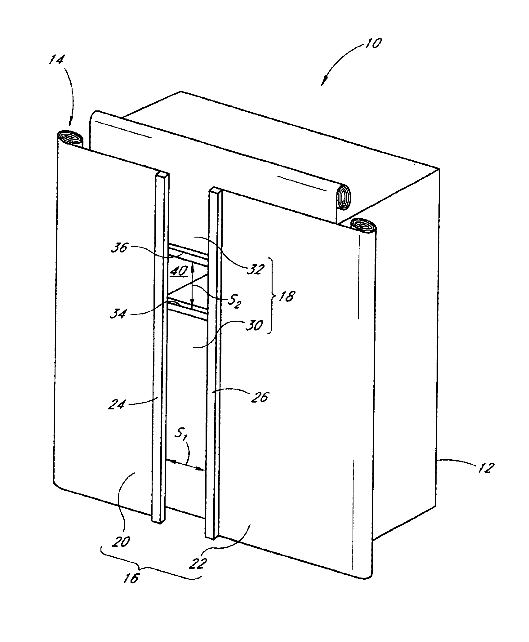
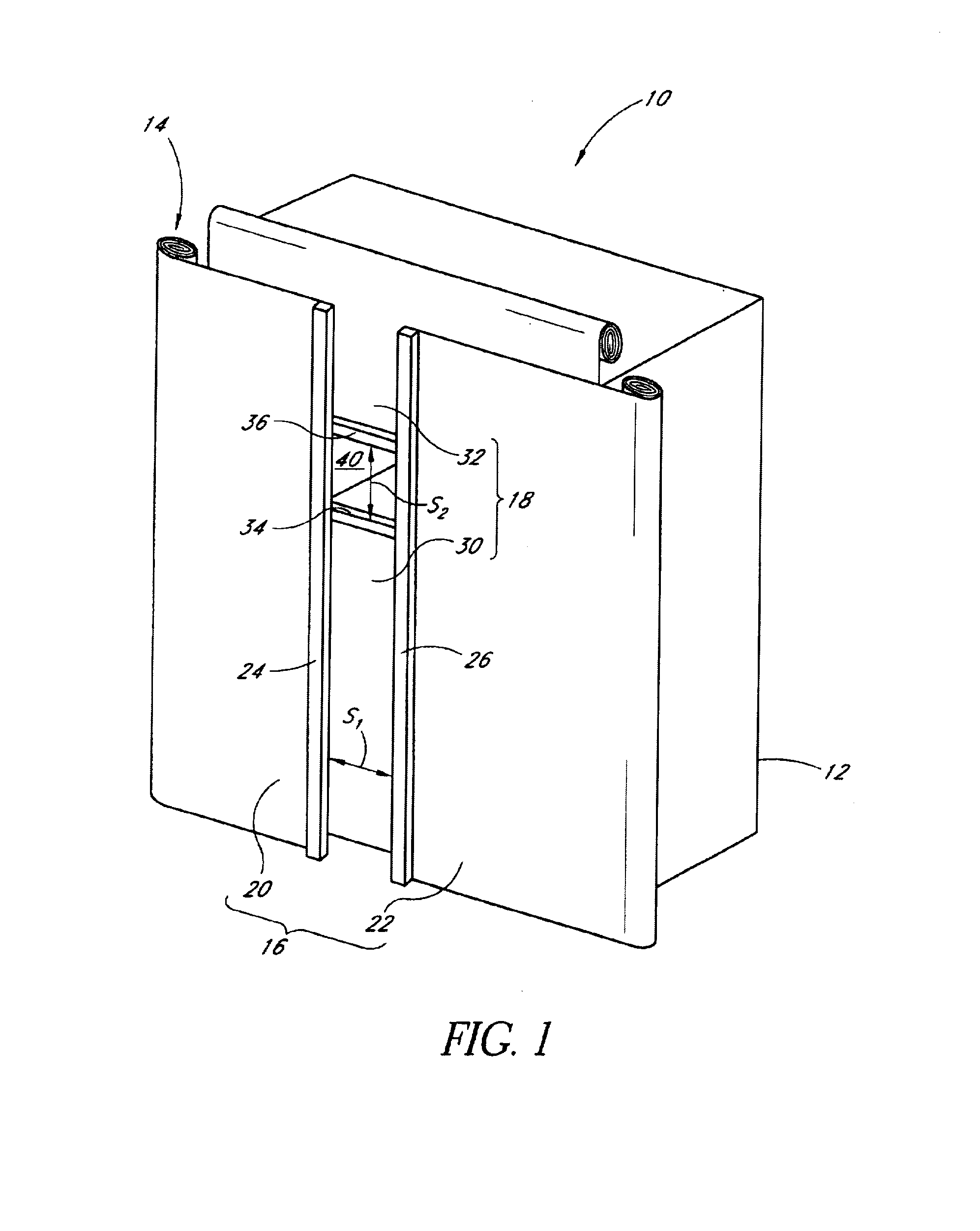
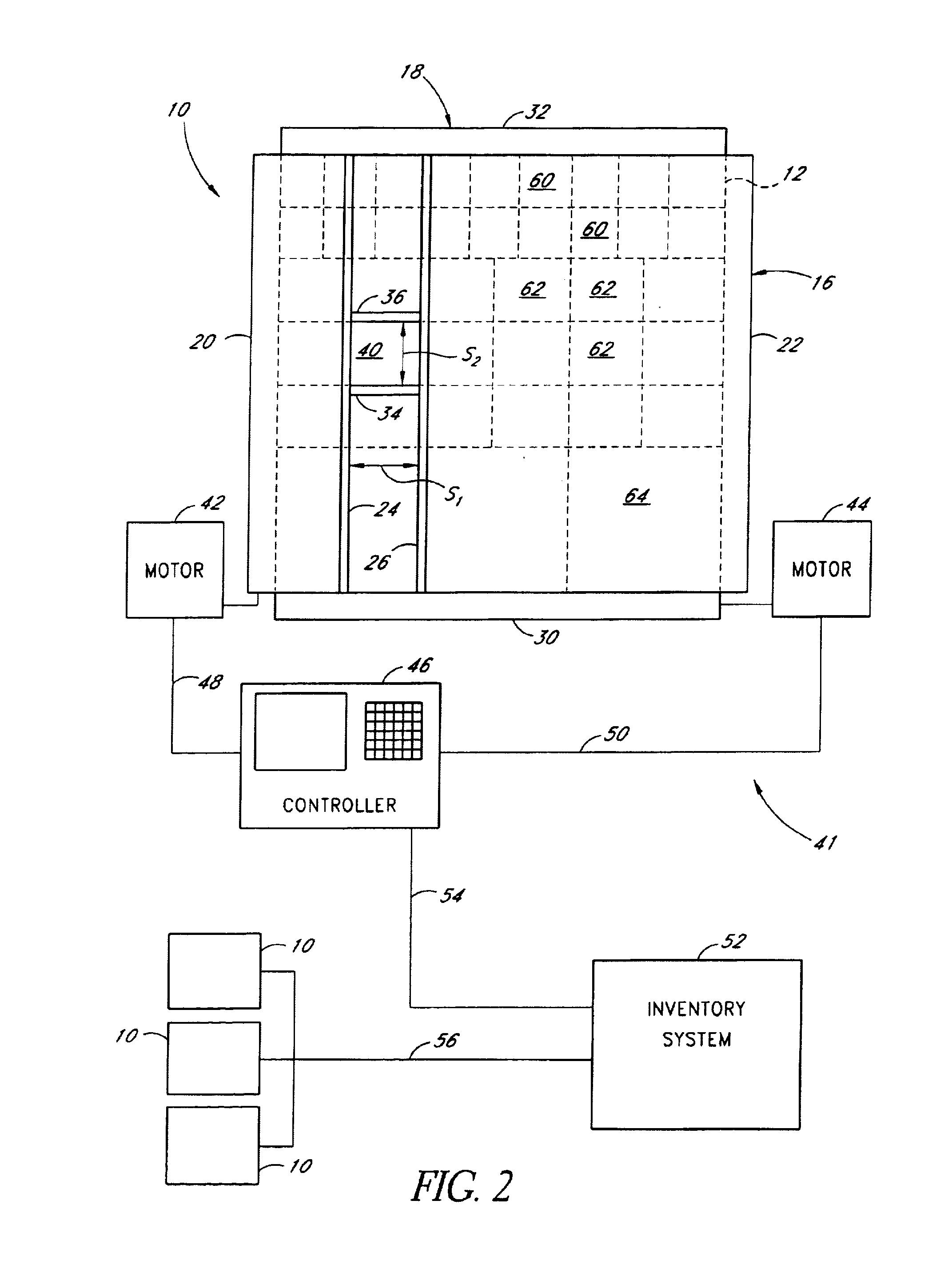
[0022]With reference to FIG. 1, a preferred dispensing apparatus 10 is illustrated. Desirably, the dispensing apparatus 10 includes a storage unit, such as a cabinet 12, which is configured to store a plurality of supply items, such as industrial supplies or office supplies, for example. An enclosure arrangement 14 encloses a front side of the cabinet 12 and is configured to selectively permit access to a portion of the supply items within the cabinet 12.

[0023]The cabinet 12 may take on a variety of configurations. For example, the cabinet 12 may be built specifically for use with a particular enclosure, such as the illustrated enclosure 14. The cabinet 12 may even be integrated with the enclosure 14. Alternatively, the cabinet 12 may be one of a variety of standard configurations suitable for storing objects, such as industrial or office supply items, and the enclosure 14 may be adapted for use with such a standard cabinet 12. Further, a standard storage unit, comprising a number o...


PUM


Abstract

A controlled access dispensing unit arranged to permit selective access to supply items within a portion of the dispensing unit. Preferably, the dispensing unit includes a cabinet arranged to hold a plurality of supply items. An enclosure assembly desirably includes a first panel and a second panel positioned in a plane substantially parallel to and aligned with a plane defined by the first panel. The two panels each comprise an opening that together defines a variable size and moveable access opening.

Description

BACKGROUND OF THE INVENTION[0001]1. Field of the Invention[0002]The present invention generally relates to dispensing systems and dispensing methods. More particularly, the present invention relates to controlled access dispensing systems and related methods especially suited for use in industrial supply applications.[0003]2. Description of the Related Art[0004]In many business environments, the immediate availability of supply items is critical to the overall efficiency of the company. For example, in manufacturing companies, if certain consumable supply items (e.g., drill bits, cutting tools, commonly-replaced spare parts, etc.) are unavailable, production may be entirely shut down until such items may be procured. Accordingly, accurate management of supply item inventory is very important. In addition, controlled access to such supply items is often desirable to ensure that recorded inventory levels are accurate and to ensure that only authorized personnel have access to certain ...

Claims


Application Information

Patent Timeline
IPC IPC(8): E06B9/15B65G1/137A47B63/06A61J7/00
CPCA47B63/06
Inventor GODLEWSKI, PETER
Owner NEXIANT
Learn More