Concentrically recording auxiliary information on non-data area of a disk-like recording medium

a technology of auxiliary information and recording medium, which is applied in the direction of recording signal processing, instruments, television systems, etc., can solve the problems of data loss, data cannot be reproduced, reproduced data is lost, etc., and achieve the effect of reliable data reproduction

Active Publication Date: 2006-02-07
SONY CORP
View PDF13 Cites 27 Cited by
  • Summary
  • Abstract
  • Description
  • Claims
  • Application Information

AI Technical Summary

Benefits of technology

[0010]The present invention has been made in view of the above, and it is accordingly

Problems solved by technology

However, if the PLL loses synchronism in reproducing the data recorded in the BCA due to some defect, for example, the data cannot be reproduced until the PLL regains synchronism.
This means that reproduced data is lost for a period when the synchronism of the PLL is lost.
Also, if a synchronization signal (sync) is lost once due to a defect or the like, data may be lost until a next synchronization signal

Method used


Image

  • Concentrically recording auxiliary information on non-data area of a disk-like recording medium
  • Concentrically recording auxiliary information on non-data area of a disk-like recording medium
  • Concentrically recording auxiliary information on non-data area of a disk-like recording medium

Examples


second embodiment

[0102]As a second embodiment, modulation of disk ID information using a 4-1 modulation for recording will next be described.

[0103]FIG. 12 shows a disk ID recording format in this case.

first embodiment

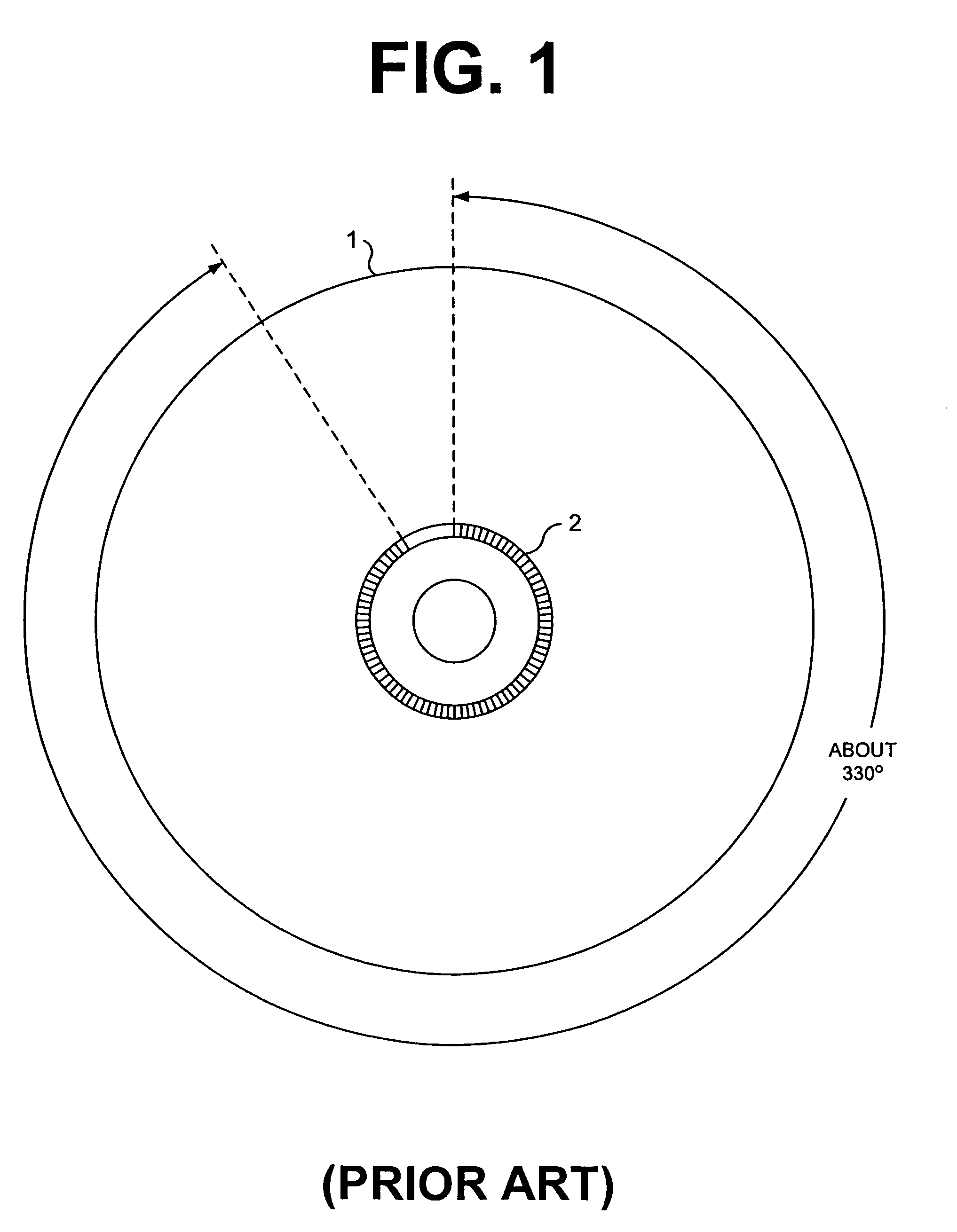
[0104]Also in this case, as in the first embodiment, the circle of the BCA 26A of the optical disk 26 is divided into three equal parts, thereby forming three blocks. Each of the blocks is formed by two frames each having a sync block SA or SB at the front. Each of the frames has a frame sync of 14 channel bits, and its information bits are 112 data bits. The 4-1 modulation converts data of 112 bits into 392 channel bits, and therefore the number of channel bits of a single frame is 406 (hence, n=3, m=2, and k=406). Disk ID information of 224 bits, that is, 28 bytes can be recorded in a single block.

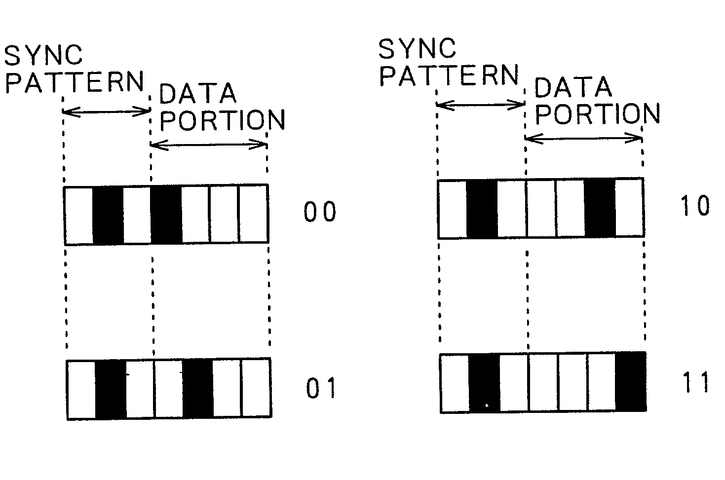
[0105]As shown in FIG. 13, the 4-1 modulation is a modulation method that modulates two data bits into seven channel bits. First three channel bits form a sync pattern denoted by “010”, and succeeding four channel bits form a data portion, which indicates data by a position of “1” within the four channel bits. When two data bits before the modulation are “00”, the data portion is “1000”;...

third embodiment

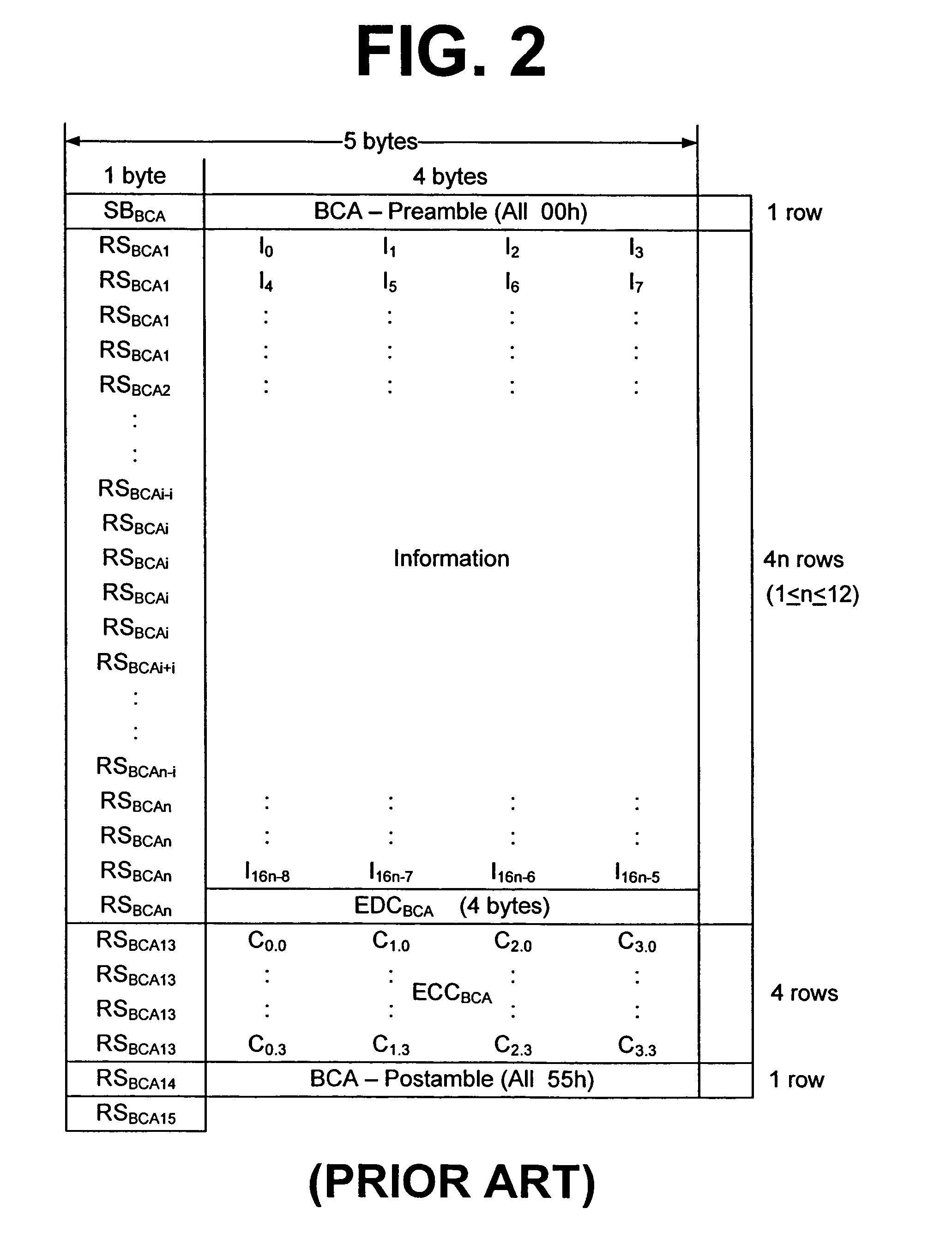
[0119]Description will next be made of a case, as a third embodiment, in which the ECC format of disk ID information recorded in the register 21 is encoded by an RS (32, 16, 17) code of GF (28) as shown in FIG. 18, 16-byte parity is added to form one block, and the same block is subjected to 4-1 modulation and then written triply around the disk.

[0120]In this case, as shown in FIGS. 19A and 19B, a sync pattern of a frame sync is formed by adding one word as sync ID to each of the sync patterns SA and SB described with reference to FIGS. 14A and 14B. A sync pattern of a frame sync thus has a total of 21 channel bits. Hence, the sync ID makes it possible to represent four kinds of sync patterns by using each of the sync patterns SA and SB and thus form a total of eight sync patterns.

[0121]Accordingly, as shown in FIG. 20, it is possible to divide one block into eight frames.

[0122]In this case, n=3 and m=8. Data of 32 bits is disposed in one frame. The data is converted into 112 channe...


PUM


Abstract

Disclosed is a disk-like recording medium, a disk recording apparatus and a disk recording method, and a disk playback apparatus and a disk playback method. Disk ID is recorded over a circle of a burst cutting area on an optical disk. The circle is divided into n blocks, each of the blocks is divided into m frames, and ID information is recorded in each of the frames with k channel bits.

Description

BACKGROUND OF THE INVENTION[0001]The present invention relates to a disk-like recording medium, a disk recording apparatus and a disk recording method, and a disk playback apparatus and a disk playback method, and particularly to a disk-like recording medium, a disk recording apparatus and a disk recording method, and a disk playback apparatus and a disk playback method that make it possible to reproduce auxiliary information of a disk reliably.[0002]As write-once or rewritable disks are spread, data replication of which is prohibited (for example contents data such as music data and video data protected by copyright or the like) may be illegally copied. On a DVD (Digital Versatile Disk), for example, a BCA (Burst Cutting Area) is provided to prevent illegal copying between disks.[0003]The BCA provided on a DVD will be described with reference to FIG. 1. A BCA 2 of a DVD 1 (DVD-ROM (Read Only Memory) or DVD-RAM (Random Access Memory)) is irradiated with pulse laser light of a YAG (y...

Claims


Application Information

Patent Timeline
IPC IPC(8): G11B7/0045G11B7/007G11B7/013G11B7/30G11B20/10G11B20/12G11B20/14G11B23/00G11B27/19G11B27/24G11B27/30
CPCG11B7/00736G11B19/122G11B20/00115G11B20/0021G11B20/00268G11B20/1217G11B20/1252G11B20/1403G11B20/1426G11B20/1803G11B23/0042G11B27/19G11B27/24G11B27/322G11B7/013G11B2220/2562G11B20/00086G11B27/3027G11B2020/122G11B2020/1222G11B2020/1244G11B2020/1265G11B2020/1287G11B2220/216G11B2220/218G11B2220/2529G11B2220/2537G11B2220/2545G11B7/007
Inventor SENSHU, SUSUMU
Owner SONY CORP
Why Eureka
Try Eureka