Pattern generation circuit, multi-path detection circuit employing the same and multi-path detection method

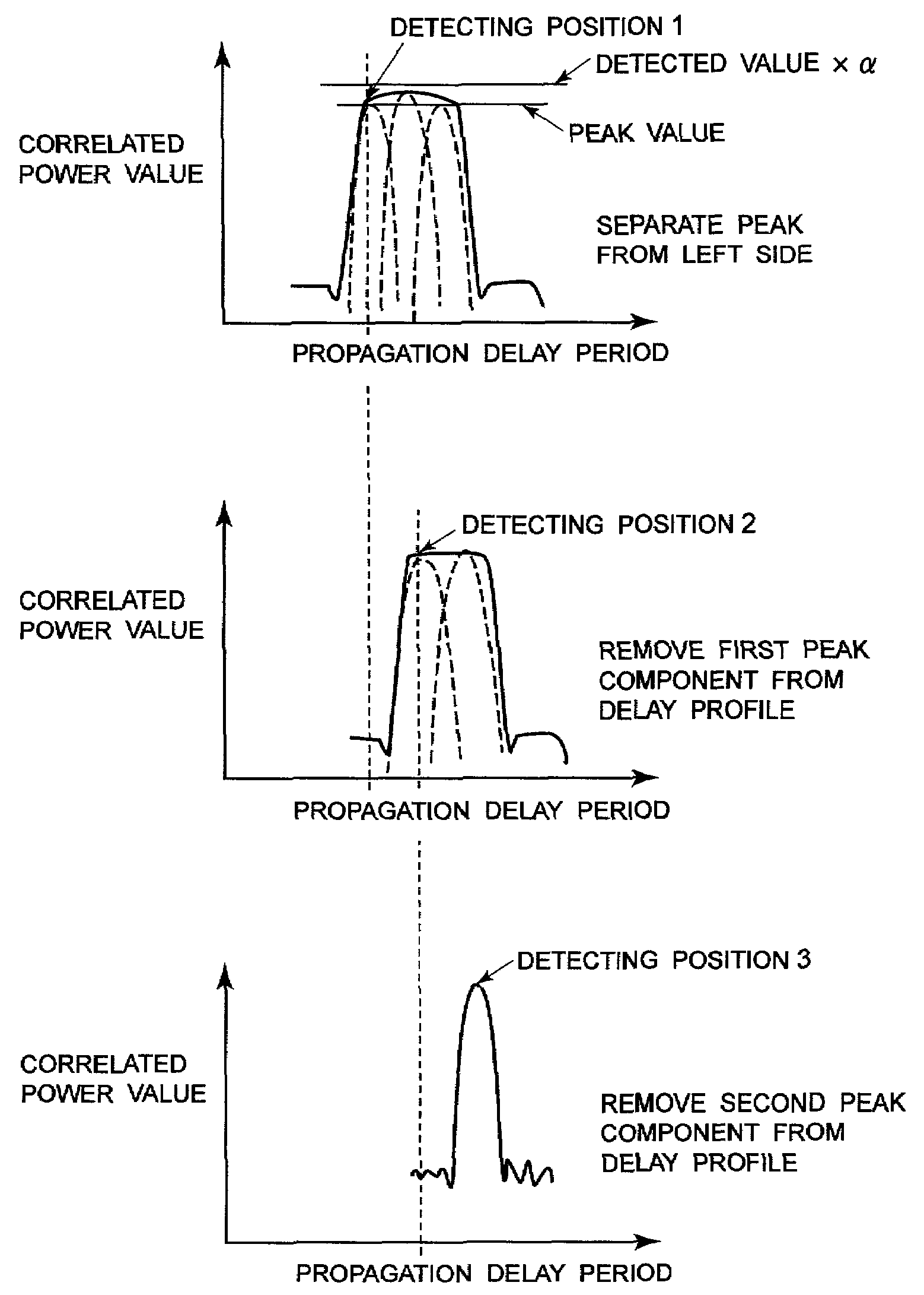
a multi-path detection and pattern generation technology, applied in phase-modulated carrier systems, amplitude demodulation, digital transmission, etc., can solve the problems of significant degraded reception performance, difficult to detect the correct path position, and inability to identify the accurate path position of the sample point, so as to improve the reception performance

Inactive Publication Date: 2006-02-07
NEC CORP
View PDF19 Cites 25 Cited by
  • Summary
  • Abstract
  • Description
  • Claims
  • Application Information

AI Technical Summary

Benefits of technology

[0033]Accordingly, even when the interval of the correlated peaks (path) is narrow to cause overlap on the delay profile, the multi-pa...

Problems solved by technology

However, when intervals of respective multi-path is narrow, a plurality of paths can overlap on the delay profile to make it difficult to detect correct path position.
However, when interval of the paths is small as shown in FIG. 5C, paths cause overlap to make it impossible to identify which sample point is the accurate path position.
When the path position cannot be detected accurately, reception performance is degraded significantly.
Also, in the foregoing method, the dete...

Method used


Image

  • Pattern generation circuit, multi-path detection circuit employing the same and multi-path detection method
  • Pattern generation circuit, multi-path detection circuit employing the same and multi-path detection method
  • Pattern generation circuit, multi-path detection circuit employing the same and multi-path detection method

Examples


Embodiment Construction

[0050]The present invention will be discussed hereinafter in detail in terms of the preferred embodiment of the present invention with reference to the accompanying drawings. In the following description, numerous specific details are set forth in order to provide a thorough understanding of the present invention. It will be obvious, however, to those skilled in the art that the present invention may be practiced without these specific detailed. In the other instance, well known structure are not shown in detail in order to avoid unnecessary obscurity of the present invention.

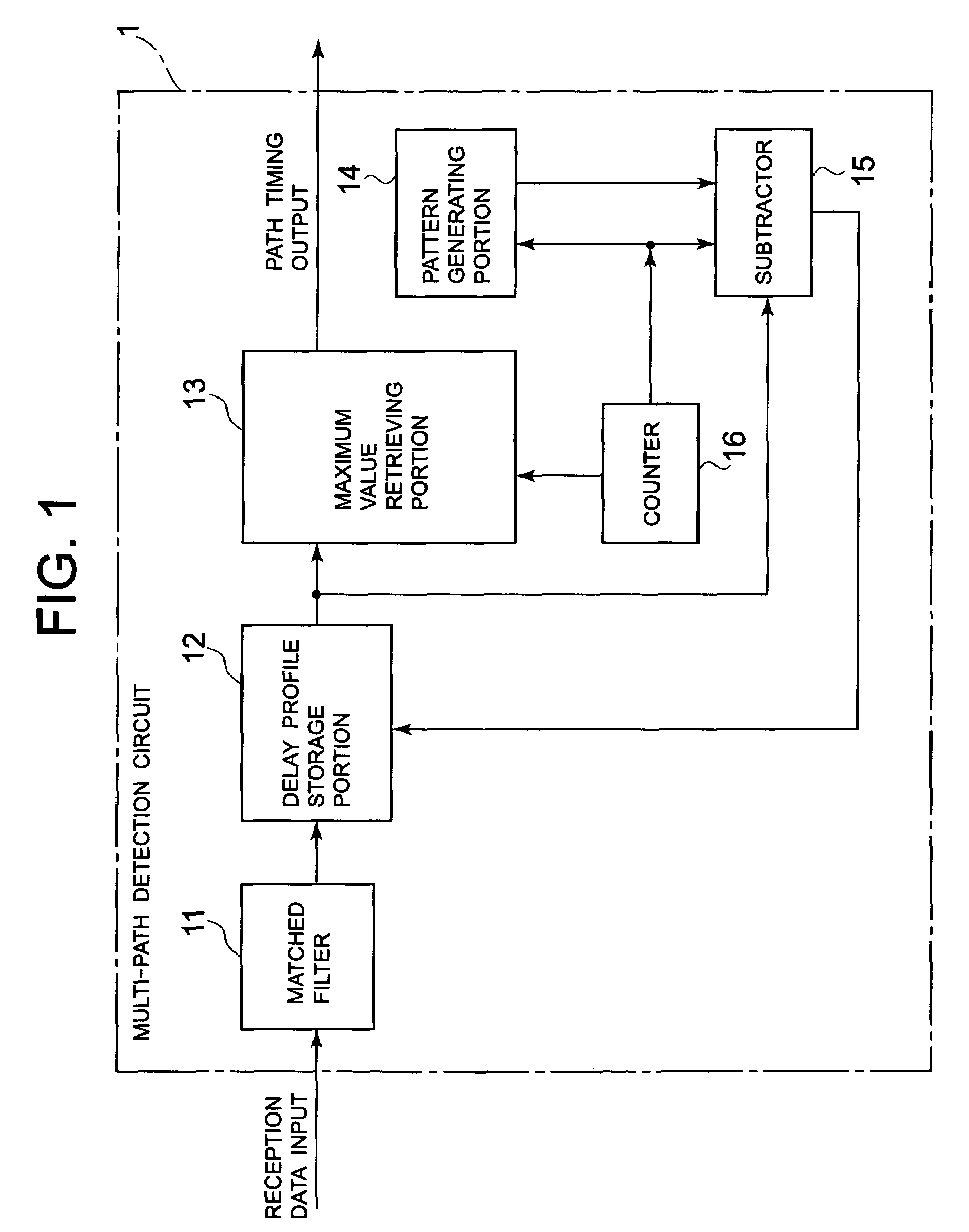
[0051]FIG. 1 is a block diagram showing a construction of one embodiment of a multi-path detection circuit according to the present invention. As shown in FIG. 1, the shown embodiment of the multi-path detection circuit 1 is constructed with a matched filter 11, a delay profile storage portion 12, a maximum value retrieving portion 13, a pattern generating portion 14, a subtractor 15 and a counter 16.

[0052]The ...


PUM


Abstract

A multi-path detection circuit can improve path detection accuracy in the environment where the path is located close in the extent of one chip in the multi-path detection circuit of CDMA type receiver unit. The multi-path detection circuit has generating means for generating a logic pattern of a correlated peak in the delay profile, and removing means for removing a power component of the detected correlated peak from the delay profile using the logical pattern of the correlated peak generated by the generating means.

Description

BACKGROUND OF THE INVENTION[0001]1. Field of the Invention[0002]The present invention relates to a pattern generation circuit, a multi-path detection circuit employing the same and a multi-path detection method. More particularly, the invention relates to a detection method of a multi-path position for determining a reception timing of a finger of a RAKE receiver employed in a code division multiple access (CDMA) system (spread spectrum system).[0003]2. Description of the Related Art[0004]Conventionally, as a path timing detection circuit of this kind, there is a circuit to be realized by measuring a delay profile of a propagation path by correlating operation of a reception signal and a spread code using a sliding correlator or matched filter and by detecting a correlation peak amount of the delay profile.[0005]However, when intervals of respective multi-path is narrow, a plurality of paths can overlap on the delay profile to make it difficult to detect correct path position.[0006]...

Claims


Application Information

Patent Timeline
IPC IPC(8): H04B1/69H04B1/10H04B1/707H04B1/7107H04B1/7113H04L27/22
CPCH04L27/22H04B1/7113H04B1/709H04B1/7117
Inventor OHSUGE, MICHIHIRO
Owner NEC CORP
Why Eureka
Try Eureka