
Adapted phase noise estimation and compensation

a phase noise estimation and compensation technology, applied in the direction of line-transmission details, pulse techniques, transmission monitoring, etc., can solve the problems of time-varying distortions, troublesome, and more difficult to sort out the “true” transmitted signal at the receiving end

Inactive Publication Date: 2006-02-07
LEGEND SILICON
View PDF3 Cites 5 Cited by
  • Summary
  • Abstract
  • Description
  • Claims
  • Application Information

AI Technical Summary

Benefits of technology

[0004]These needs are met by the invention, which receives a frame with a data sequence including two or more transmission parameter symbol (TPS) sets from a transmission channel. A TPS choice procedure analyzes effects of the transmission and selects one of the TPS sets for further proce...

Problems solved by technology

When a signal, even an ideal signal, is transmitted, the transmission channel and signal processing devices introduce signal distortions (multipath, noise, phase noise, etc.), which makes it more difficult to sort out the “true” transmitted signal at the receiving end.
Distortions introduced by the transmission channel distortion(s) are time varying and are especially troublesome when dealing with certain classes of signals, such as ofdm signals.

Method used


Image

  • Adapted phase noise estimation and compensation
  • Adapted phase noise estimation and compensation
  • Adapted phase noise estimation and compensation

Examples


Embodiment Construction

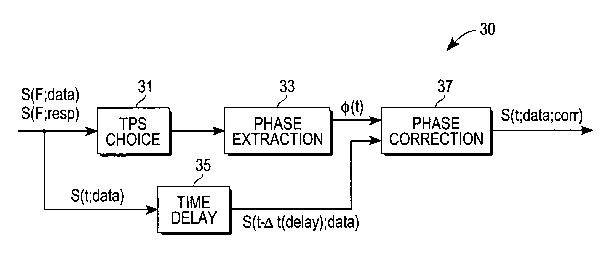
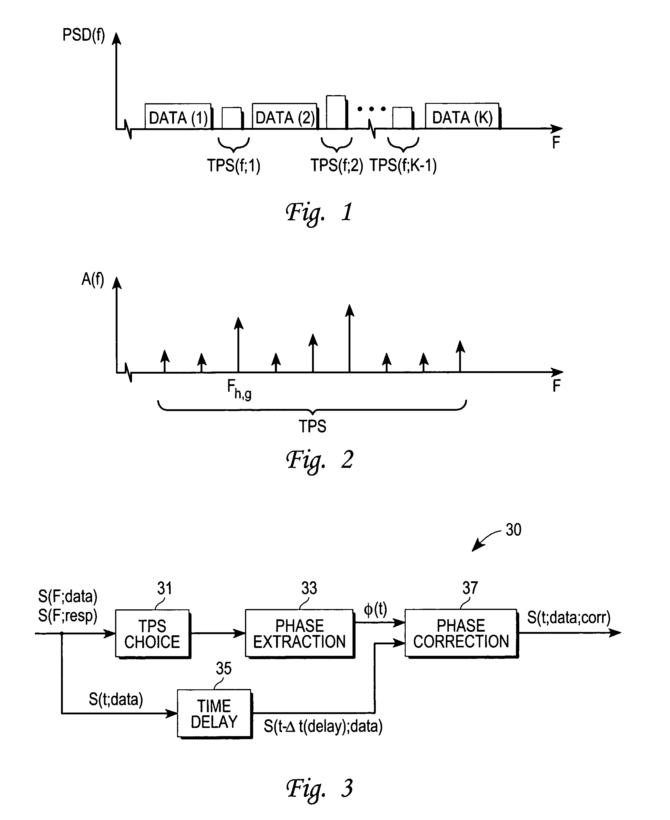
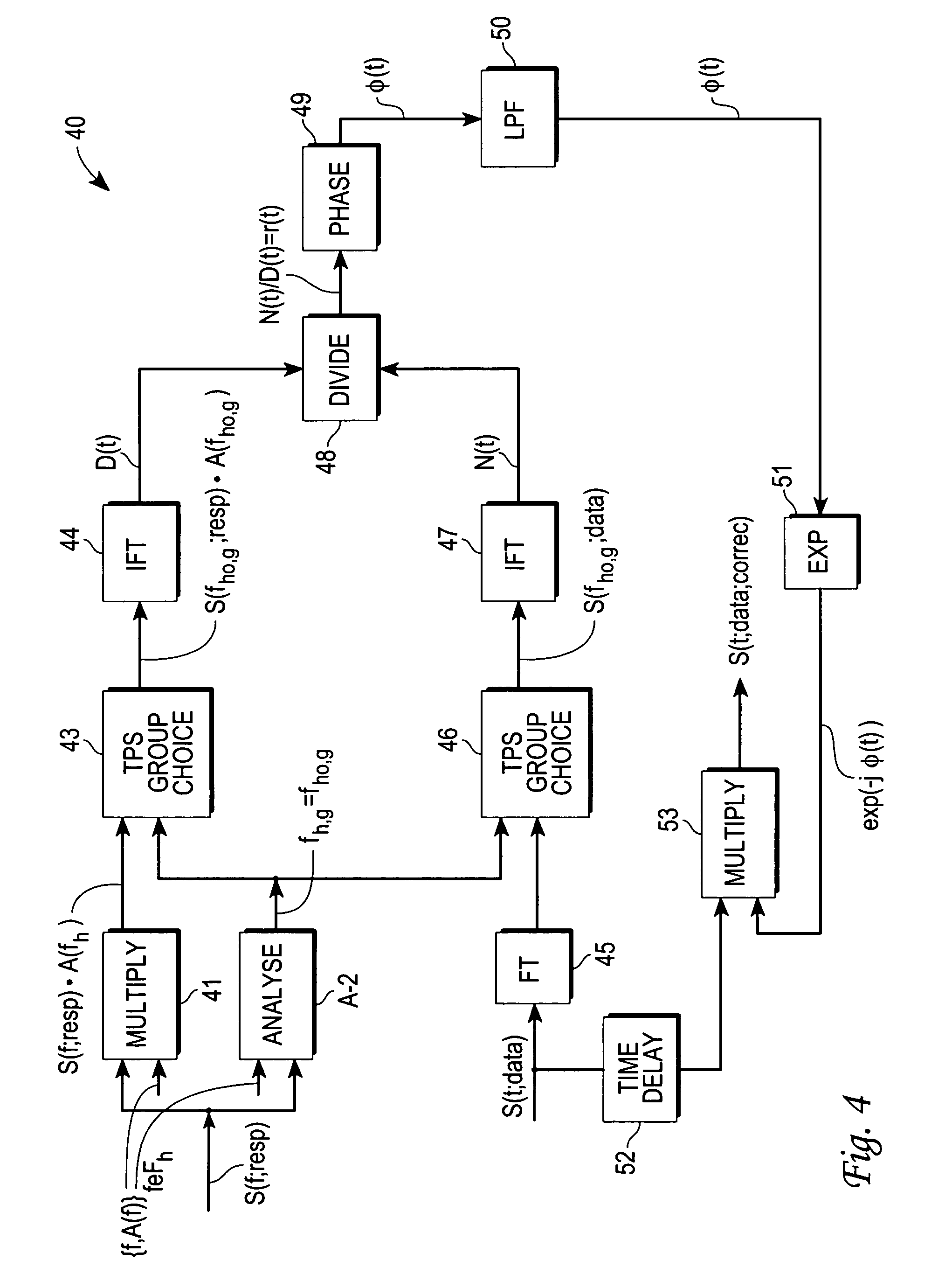
[0010]A frequency domain (FD) signal (e.g., a frame), generated and transmitted by a transmitter system, includes a known indicium portion of the frame, which identifies the particular frame, and a remainder or data portion. Where the signals are ofdm frames, for example, the indicium portion may be a pseudo-noise component or another signal component that allows identification of the particular frame. The data portion of a more general “TPS frame” is expressed as K data segments, denoted Data(k) (k=1, . . . , K; K≧2), of a data sequence in the frequency domain, with each consecutive pair of data segments being separated by, or associated with, a known transmission parameter symbol (TPS) set, defined in the frequency domain and expressed as a sequence of pairs of frequency and complex amplitude values {f,A(f)}fεFh (h=1, . . . , K-1). Each TPS set corresponds to a selected group frequency, f=fh,g, and to a group of frequencies adjacent to the group frequency, as illustrated in a powe...


PUM


Abstract

Method and system for adaptively estimating and compensating for phase noise error in a received signal s(t;data). A plurality of transmission parameter symbol (TPS) sets, each with a representative TPS group frequency, are incorporated in the signal before transmission. Received channel response amplitudes are analyzed to select a particular TPS frequency group, and inverse Fourier transforms, N(t) and D(t), are computed for these chosen signals. A complex ratio, r(t)=N(t) / D(t), is computed and used to determine a phase angle φ(t). A phase noise error compensated, time domain signal, equal to exp{−jφ(t)}·s(t−Δt(delay);data) is provided.

Description

FIELD OF THE INVENTION[0001]This invention relates to compensation for phase irregularities in a received signal, such as an ofdm signal.BACKGROUND OF THE INVENTION[0002]When a signal, even an ideal signal, is transmitted, the transmission channel and signal processing devices introduce signal distortions (multipath, noise, phase noise, etc.), which makes it more difficult to sort out the “true” transmitted signal at the receiving end. Distortions introduced by the transmission channel distortion(s) are time varying and are especially troublesome when dealing with certain classes of signals, such as ofdm signals. Some of the methods previously used to estimate the channel distortion require extensive use of supplementary signals, such as pilot signals, do not take account of variation of the distortion with time (frame-to-frame) or variation of the distortion with signal frequency.[0003]What is needed is an approach that provides compensation for distortions of phase and other signa...

Claims


Application Information

Patent Timeline
IPC IPC(8): H04L27/06
CPCH04L27/2657H04L27/2695H04L27/2675
Inventor LIU, QINYANG, LIN
Owner LEGEND SILICON
Learn More