Mattress structure

a mattress and structure technology, applied in the field of mattresses, can solve the problems of cross-member addition, increased horizontal tension strength and shear strength of the material, and increased cross-members, and achieve the effect of improving the pressure distribution

Active Publication Date: 2006-02-14
SABIN JEFFREY M
View PDF33 Cites 16 Cited by
  • Summary
  • Abstract
  • Description
  • Claims
  • Application Information

AI Technical Summary

Benefits of technology

[0008]It is therefore an object of the present invention to provide a mattress having improved pressure distribution with varied support characteristics at targeted areas.
[0010]It is another object of the present invention to provide a mattress that conforms well to the body to attain a buoyant effect.
[0012]It is yet another object of the present invention to provide a mattress that achieves the above-objects while being inexpensive to manufacture and customize.

Problems solved by technology

A main problem with existing mattresses is that when the spring quantities are increased, cross members are added due to the instability of the spring ends.
Another problem with existing mattresses is that the spring coils are exposed so that the mattress requires more insulation between the spring coils and the body.
A main problem with these designs is related to the horizontal tension strength and shear strength of the material.
Another problem with such designs is that the spring rate is generally constant throughout the mattress surface.
Therefore, the spring rate can not be varied in different sections of a mattress.
Another problem associated with viscoelastic (memory) foam is that it is slow to respond to body movement, as a person turns or moves in bed, and this can limit or make movement more difficult once the foam forms a set.

Method used


Image

  • Mattress structure
  • Mattress structure
  • Mattress structure

Examples


first embodiment

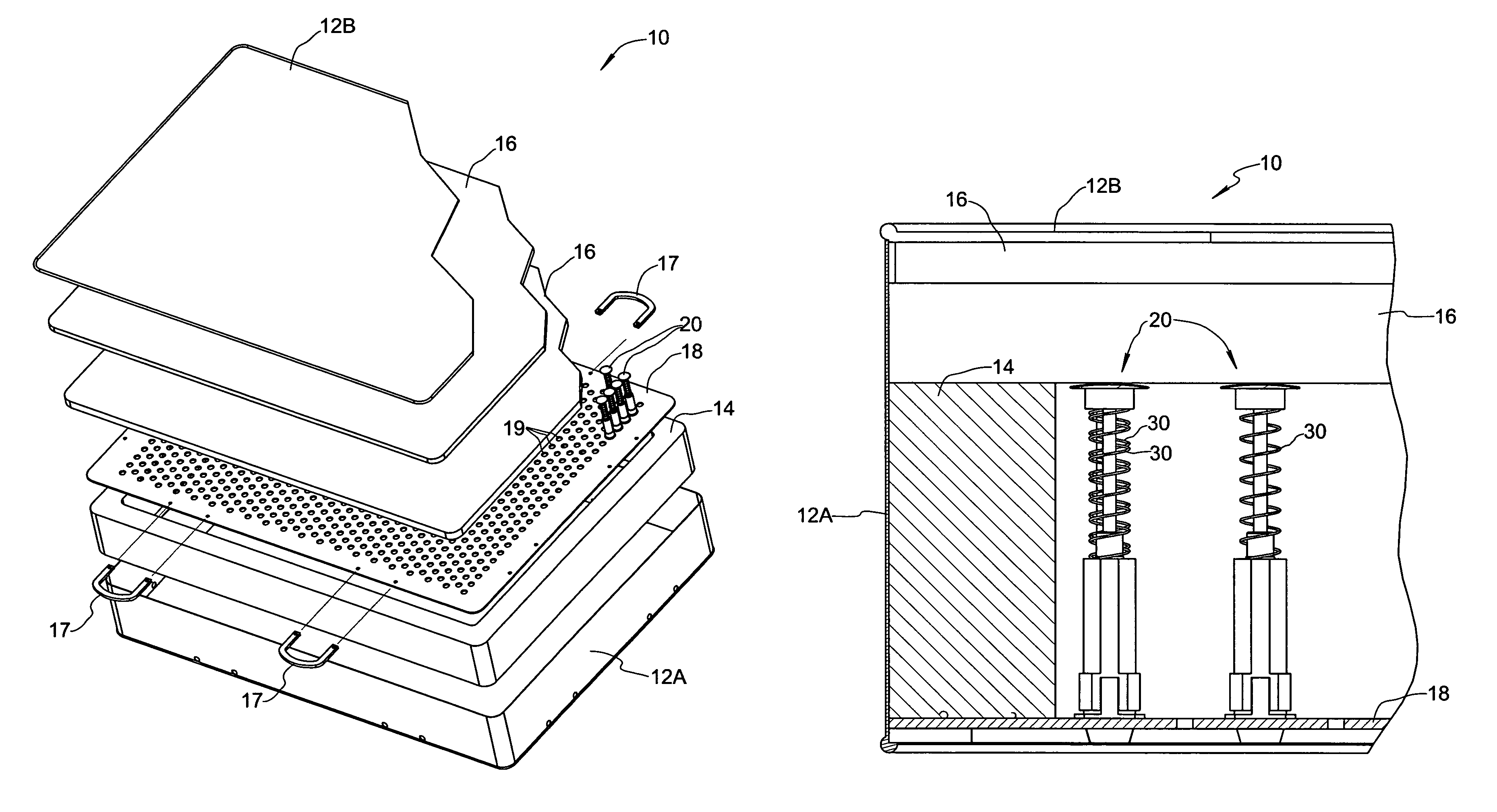
[0038]FIGS. 4–6 show a spring assembly 20 formed in accordance with the present invention. Spring assembly 20 generally comprises a tubular mounting member 22 fixed to the support plate 18, a sliding cap 26 axially movable relative to mounting member 22, and a spring 30 acting between mounting member 22 and sliding cap 26, wherein spring 30 is axially compressible when sliding cap 26 is forced in an axial direction toward support plate 18.

[0039]Mounting member 22 includes a tapered catch plug 22A at a lower end thereof, a neck 22B adjacent to catch plug 22A, and a stabilizing flange 22C adjacent to neck 22B. Catch plug 22A is provided with at least one slot 22D enabling elastic compression of the catch plug so it can pass through mounting hole 19. Neck 22B has an outer diameter that corresponds to the diameter of mounting hole 19 and an axial length that corresponds to the thickness of support plate 18. As will be appreciated, the lower end of mounting member 22 is configured for sn...

second embodiment

[0050]Sliding cap 126 of the second embodiment is a tubular member that includes an open lower end having an internal shoulder surface 126A facing upwardly in opposition to downwardly facing shoulder surface 122E of mounting member 122, and a closed upper end configured to provide an internal annular groove 126B. A slot 126C is provided through the wall of sliding cap 126 to facilitate elastic expansion of the lower end during assembly of spring assembly 120. Sliding cap 126 is telescopically adjustable in an axial direction relative to mounting member 122 and is guided by sliding engagement of internal surface 126D with the outer wall surface of mounting member 122. An o-ring or foam ring 127 is preferably seated circumferentially about mounting member 122 adjacent shoulder surface 122E, such that upwardly directed withdrawal of sliding cap 126 is prevented by engagement of shoulder surface 126A with o-ring 127 as shown in FIG. 9. A plurality of internal axially extending rails 126...

third embodiment

[0052]FIGS. 10 and 11 depict a spring assembly 220 formed in accordance with the present invention as having a tubular mounting member 222 fixed to the support plate 18, a sliding cap 226 axially movable relative to mounting member 222 in telescoping fashion, and a spring 230 acting between mounting member 222 and sliding cap 226, wherein spring 230 is axially compressible when sliding cap 226 is forced in an axial direction toward support plate 18.

[0053]Mounting member 222 is generally similar to mounting member 22 of the first embodiment and includes a tapered catch plug 222A at a lower end thereof, a neck 222B adjacent to catch plug 222A, and a stabilizing flange 222C adjacent to neck 222B. Catch plug 222A is provided with a slot 222D enabling elastic compression of the catch plug so it can pass through mounting hole 19. Neck 222B has an outer diameter that corresponds to the diameter of mounting hole 19 and an axial length that corresponds to the thickness of support plate 18. T...


PUM


Abstract

A mattress comprises a support plate having a plurality of mounting holes, a plurality of independent spring assemblies individually mounted to the support plate, and a cover enclosing the support plate and the plurality of spring assemblies. Each of the spring assemblies includes a tubular mounting member fixed to the support plate preferably by snap-fit through a mounting hole in the support plate, a sliding cap axially movable relative to the mounting member, and a spring acting between the mounting member and the sliding cap, wherein the spring is axially compressible when the sliding cap is forced in an axial direction toward the support plate. A spacer of chosen length can be provided to set preload on the spring. In a “flippable” embodiment, the mounting member includes a mid-portion snap-fitted to the support plate and upper and lower portions each having a sliding cap associated therewith, wherein the spring acts between the two sliding caps. In yet another embodiment, the sliding cap is replaced by a bellows attached to the mounting member.

Description

CROSS REFERENCE TO RELATED APPLICATIONS[0001]This application claims benefit of U.S. Provisional Patent Application No. 60 / 472,936 filed May 23, 2003 and U.S. Provisional Patent Application No. 60 / 474,498 filed May 30, 2003, and the disclosures of these applications are incorporated herein by reference.FIELD OF THE INVENTION[0002]The invention relates to the field of mattresses.BACKGROUND OF THE INVENTION[0003]Typically, mattresses found in the marketplace include a series of coiled springs that are supported by cross members to keep the spring ends from bucking off axis or moving horizontally, and to achieve a certain amount of flatness. Cross members typically have small coils that are looped through the ends of the main coiled springs. If the ends are not supported by the cross members, the diameter of the spring must be large enough to resist instability (moving horizontally) or bucking.[0004]A main problem with existing mattresses is that when the spring quantities are increase...

Claims


Application Information

Patent Timeline
Patent Type & Authority Patents(United States)
IPC IPC(8): A47C23/04A47C23/05F16F3/04A47C23/00A47C27/06A47C31/08
CPCA47C23/00A47C31/08A47C27/063A47C23/002A47C27/04A47C27/06
Inventor SABIN, JEFFREY M.
Owner SABIN JEFFREY M
Why Eureka
Try Eureka