Radial roller bearing

a technology of radial roller bearings and roller bearings, which is applied in the direction of rolling contact bearings, rotary bearings, shafts and bearings, etc., can solve the problems of easy seizure and wear in the end portion of the contact portion, and achieve the effect of enhancing the seizure resistance and wear resistance of the contact portion

Inactive Publication Date: 2006-02-14
NSK LTD
View PDF2 Cites 12 Cited by
  • Summary
  • Abstract
  • Description
  • Claims
  • Application Information

AI Technical Summary

Benefits of technology

[0006]The present invention aims at eliminating the above-mentioned drawbacks found in the conventional radial roller bearing. Accordingly, it is an object of the invention to provide a radial roller bearing which can restrict occurrence of an edge load in the contact portion between the cylindrical roller and flange portion to thereby be able to enhance the seizure resistance and wear resistance of the contact portion.

Problems solved by technology

Due to this edge load, there is applied excessively large surface pressure onto the end portion of the contact portion, with the result that seizure and wear are easy to occur in the end portion of the contact portion.

Method used


Image

  • Radial roller bearing
  • Radial roller bearing
  • Radial roller bearing

Examples


Embodiment Construction

[0022]Now, description will be given below of an embodiment of a radial roller bearing according to the invention with reference to the accompanying drawings.

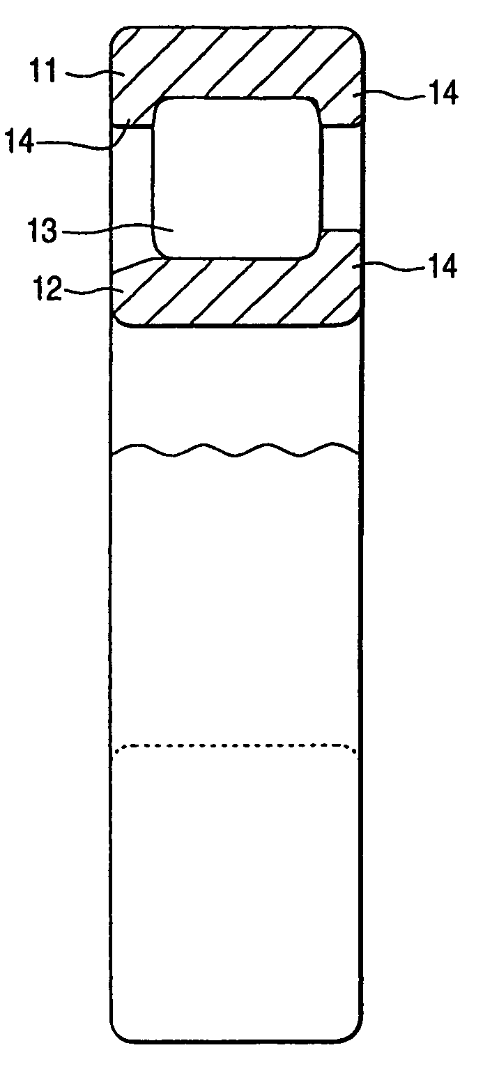
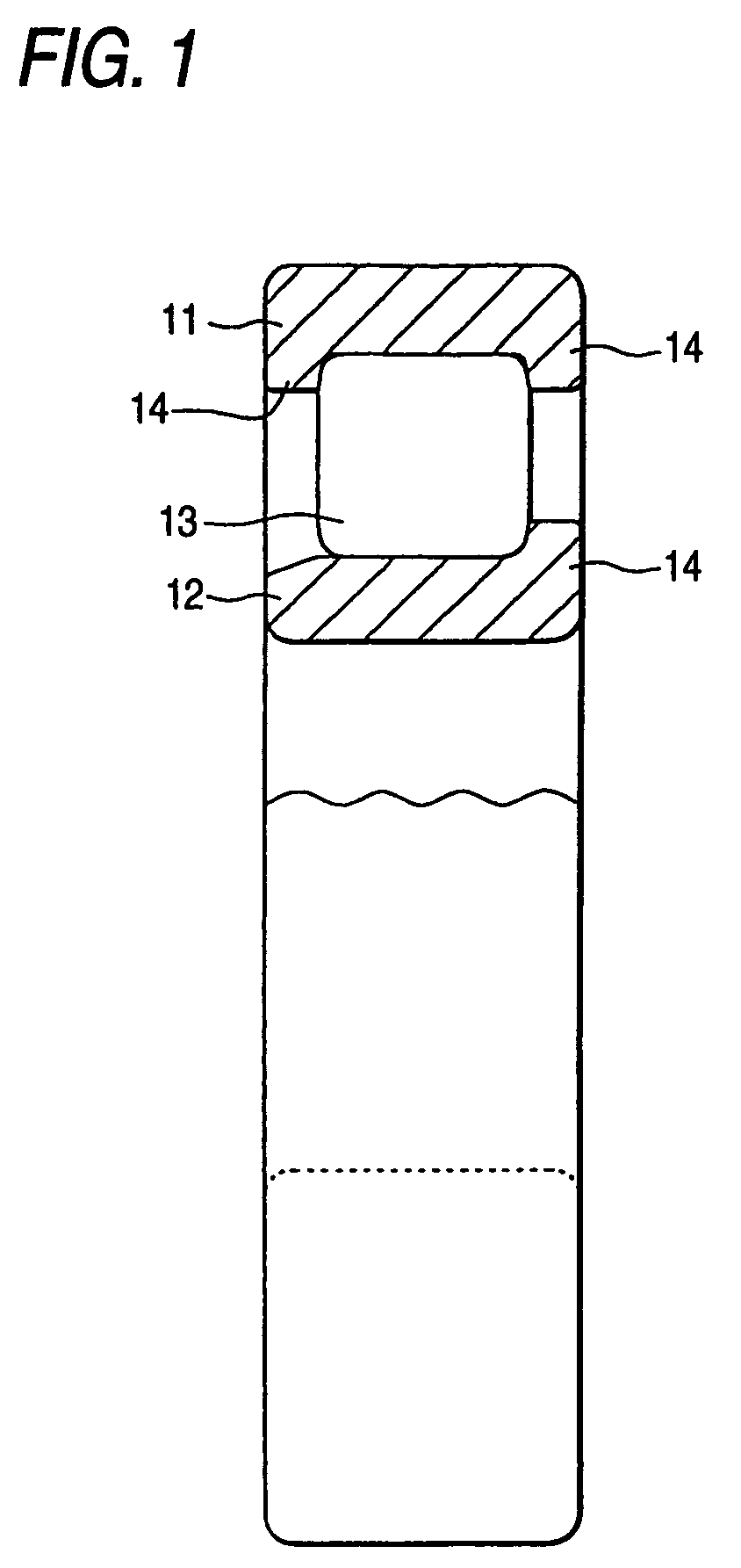
[0023]FIG. 1 is a partially sectional view of a radial roller bearing according to an embodiment (which is hereinafter referred to as the present embodiment) of the invention, and FIG. 2 is an enlarged view of a portion of FIG. 1. As shown in FIG. 1, a radial roller bearing according to the present embodiment comprises an outer ring 11, an inner ring 12 and a cylindrical roller 13.

[0024]The outer ring 11 and inner ring 12 are respectively formed in a ring shape and, in the end portions of these rings 11, 12, there are respectively formed flange portions 14 each having an opening angle δ of the order of 0.0835° (5 arcminutes) to 3°. The flange portions 14 are respectively disposed so as to be opposed to the end face of the cylindrical roller 13. In the end face of the cylindrical roller 13, there is formed a circular-ring-shaped...


PUM


Abstract

A radial roller bearing has: an outer ring; an inner ring; and, a cylindrical roller interposed between the outer ring and the inner ring, the outer and inner rings respectively including flange portions formed in the end portions thereof so as to be opposed to the end face of the cylindrical roller, wherein, in the end face of the cylindrical roller, there is formed a circular-ring-shaped contact portion of the roller end having centers of curvature continuously existing on a circle which lies on a plane parallel to the end face of the cylindrical roller and also the center of the circle is on the rotation axis of the cylindrical roller.

Description

[0001]This is a continuation of application Ser. No. 10 / 287,702 filed Nov. 5, 2002 now U.S. Pat. No. 6,702,471; the disclosure of which is incorporated herein by reference.BACKGROUND OF THE INVENTION[0002]The present invention relates to a radial roller bearing and, in particular, to a radial roller bearing of a type that, in the end portion of a ring, there is formed a flange portion to be slidingly contactable with the end face of a cylindrical roller.[0003]In a radial roller bearing using a cylindrical roller as a rolling element, in the end portion of a ring, there is formed a flange portion; that is, the end face of the cylindrical roller is slidingly contacted with the present flange portion to thereby control the attitude of the cylindrical roller when it is skewed, or guide the cylindrical roller in the circumferential direction of the ring, or support an axial load applied to the cylindrical roller.[0004]In the radial roller bearing of this type, in case where only the radi...

Claims


Application Information

Patent Timeline
Patent Type & Authority Patents(United States)
IPC IPC(8): F16C19/26F16C33/34F16C33/58
CPCF16C19/225F16C19/26F16C33/585F16C33/34F16C2240/40
Inventor SAKODA, HIRONARINATSUMEDA, SHINICHIMURAI, TAKASHI
Owner NSK LTD
Why Eureka
Try Eureka