
Material for sliding parts having self lubricity and wire material for piston ring

a technology of self-lubricating and wire material, which is applied in the field of sliding parts materials, can solve the problems of poor seizure resistance properties, unsolved problems such as cost of surface treatment and aluminum adhesion, and the second ring of steel has not made good progress, so as to improve workability and machinability of steel. , the effect of rapid precipitation

Inactive Publication Date: 2006-03-09
HITACHI METALS LTD
View PDF6 Cites 10 Cited by
  • Summary
  • Abstract
  • Description
  • Claims
  • Application Information

AI Technical Summary

Benefits of technology

The present invention provides a material for sliding parts that has excellent wear resistance and low friction coefficient properties. The material is made of a steel that contains specific amounts of carbon, silicon, and other elements such as molybdenum, tungsten, vanadium, and copper. The steel also contains graphite particles that have a specific size and distribution. The invention also provides a wire material for piston rings that has a specific metal structure with graphite precipitates, which improves seizure resistance and lowers friction coefficient. The invention addresses the problem of poor seizure resistance and high friction coefficient of sliding parts, which are exposed to severe conditions in their environments. The invention provides a solution to improve durability and workability of sliding parts.

Problems solved by technology

Steel piston rings are outstandingly excellent in mechanical properties and wear resistance property than those of cast iron rings, but have poor seizure resistance property, which is one of reasons that second rings of steel have not been made good progress.
But, such unsolved problems still remain as a cost for surface-treatment and aluminum adhesion which occurs at the interface between a piston and a piston ring.
As countermeasures against such disadvantages, the patent literature No. 2 proposes surface-treatments such as PVD, whereas an increase of a manufacturing cost cannot be avoided according to such surface-treatment.

Method used


Image

  • Material for sliding parts having self lubricity and wire material for piston ring
  • Material for sliding parts having self lubricity and wire material for piston ring
  • Material for sliding parts having self lubricity and wire material for piston ring

Examples


example 1

[0089] Several steels were melted in a high-frequency induction furnace in the open air, adjusted to chemical compositions in Table 1, and cast to ingots of 220 mm×220 mm in section size. In Table 1, Specimen No. 1 to 6 satisfy definitions of the present invention. Specimen No. 11 to 16 are comparative steels, wherein Specimen No. 16 corresponds to JIS SUS440B, used for conventional piston rings.

TABLE 1Chemical compositions (mass %)SpecimenMo +No.CSiMnCrAlSMoWVMo + WW + VCaNiCuCoFe10.421.852.830.250.310.290.50.50.50.00022.960.1bal.20.660.931.210.450.780.132.02.91.24.96.10.00100.22.8bal.30.791.521.980.311.480.067.25.112.312.30.00300.31.1bal.40.982.321.030.211.030.127.510.00.517.518.00.00600.51.3bal.51.422.781.010.011.910.032.93.07.97.90.00982.10.8bal.60.881.551.050.031.031.051.051.10.80.8bal.110.551.490.710.211.02.03.03.00.0003bal.121.000.250.311.481.531.83.45.25.2bal.130.551.510.721.010.354.89.914.714.70.00020.8bal.140.781.230.460.031.340.064.22.16.36.30.00502.53bal.150.551.350.55...

example 2

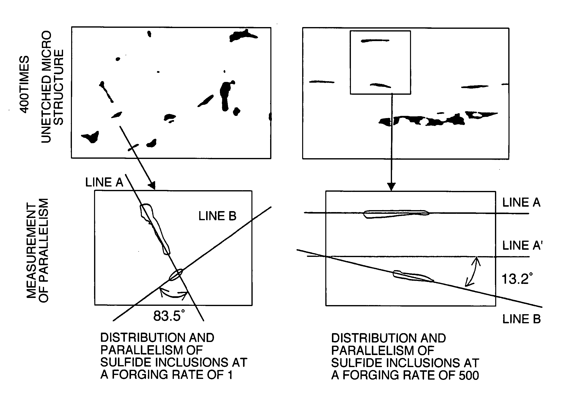
[0098] Each of Specimen No. 1 and 15 in Table 1 was hot-rolled to a coil of 5.5 mm in diameter and then processed to a flat wire profile of 1.5 mm×3.1 mm in section size by drawing and cold-rolling. Specimen No. 1 was formed to the objective profile without troubles, but Specimen No. 15 was broken in a drawing step due to its poor cold-workability. A metal structure of each billet of Specimen No. 1 and 15 was microscopically observed in an undrawn state along a direction perpendicular to a rolling direction and analyzed for measuring the area rate of nonmetallic inclusions. The area rate of nonmetallic inclusions was 1.86% in Specimen No. 1, but 2.23% in Specimen No. 15. Comparison of the observation results indicates that breakage of Specimen No. 15 was caused by excess nonmetallic inclusions at a ratio above 2.0% in addition to excess sulfur.

example 3

[0099] Each of Specimen No. 1 to 6, 11 and 12 was processed to a flat wire profile of 1.5 mm×3.1 mm in section size under the same condition as Example 2, heated 30 minutes at 1000° C., quenched and tempered to hardness of around 510 HV. The processed test piece was machined 10 times by a grinding cutter at a rotational frequency of 10000 r.p.m and a feed rate of 1 mm / second, for investigating occurrence frequency of burrs. Table 4 shows test results on the occurrence frequency of burrs.

TABLE 4SpecimenOccurrence frequency ofNo.burrsNote10Invention20specimens30405067118Comparative1210specimens

[0100] Occurrence of burrs was detected in any of Specimen No. 11 and 12, but no burrs occurred in any of Specimen No. 1-5, to which S was added at a proper ratio. The results prove that addition of S has remarkable effects on suppression of burrs. Consequently, piston rings can be manufactured with high productivity.


PUM

PropertyMeasurementUnit
particle sizeaaaaaaaaaa
sizeaaaaaaaaaa
sizeaaaaaaaaaa

Abstract

A material for use as self-lubricating sliding parts, which consists of a steel containing, by mass, from not less than 0.4% to less than 1.5% of C (carbon), 0.1 to 3.0% of Si, 0.1 to 3.0% of Mn, from inclusive zero to 0.5% of Cr, 0.05 to 3.0% of Ni, 0.3 to 2.0% of Al, 0.3 to 20% in total (Mo+W+V) of at least one element selected from the group consisting of Mo, W (tungsten) and V (vanadium), and 0.05 to 3.0% of Cu, wherein there can be observed graphite particles having an average particle size of not more than 3 μm in a section of the metal structure of the steel. The steel is also used as piston rings. In the steel, the graphite particles observed in the structural section occupy an area rate of not less than 1% in the overall area of the structural section, and have an average particle size of not more than 3 μm. The steel may further contain not more than 0.3% of S and / or not more than 0.01% of Ca. The steel is subjected to nitriding treatment for use.

Description

TECHNICAL FIELD [0001] The present invention relates to material for use as sliding parts, e.g. piston rings, cylinder liners and vanes, which are incorporated in automotive engines or other internal combustion engines, as well as usual plain bearings, roller bearings, ball bearings, gears and dies. BACKGROUND ART [0002] Materials having excellent wear resistance property have been applied so far to sliding parts such as cylinder liners and vanes. Materials for piston rings used in internal combustion engines, especially automotive engines, have been changed from cast steel to steel wire, which is processed to ring forms. In usual, the piston rings are produced in such a manner that an ingot with a predetermined composition is hot-worked to wire by forging, hot-rolling or the like, the thus obtained wire is further formed to have a given cross-sectional form corresponding to a small sectional form of a piston ring by drawing or the like, the formed wire is conditioned to have a give...

Claims


Application Information

Patent Timeline
Patent Type & Authority Applications(United States)
IPC IPC(8): C22C38/42C22C38/44C22C38/02C22C38/04C22C38/06C22C38/08C22C38/12C22C38/34C22C38/58C22C38/60
CPCC22C38/02C22C38/04C22C38/06C22C38/08C22C38/60C22C38/34C22C38/44C22C38/58C22C38/12C22C1/00
Inventor FUJITA, ETSUOKUBOTA, KUNICHIKAMASUGATA, YOSHIKIMINAGI, YOSHIHIRO
Owner HITACHI METALS LTD
Learn More