
Positive resist composition and patterning process using same

a technology of resist film and composition, applied in the field of positive resist composition, can solve the problems of deterioration in the sensitivity of the resist film, decrease in the productivity, and unsuitability, and achieve the effects of enhancing resolution, suppressing acid diffusion rate in the resist film, and enhancing sensitivity

Active Publication Date: 2014-06-19
SHIN ETSU CHEM IND CO LTD
View PDF14 Cites 20 Cited by
  • Summary
  • Abstract
  • Description
  • Claims
  • Application Information

AI Technical Summary

Benefits of technology

The present invention is related to a positive resist composition that is suitable for use in a variety of semiconductor processes. The composition contains a specific polymer compound as the base resin, which, when blended with an organic solvent, an acid-generator, a dissolution control agent, a basic compound, a surfactant, and so forth, enhances the dissolution rate of the polymer in a developer. This results in a highly sensitive resist composition with high dissolution contrast and resolution, and a large exposure margin. Additionally, the composition has excellent etching resistance and can be used for patterning processes. Dissolution control agents and basic compounds can further improve the resolution and coating properties of the resist composition. The composition may also contain an acid-generator to function as a chemically amplifying resist composition. Other components that can be added include organic solvents, basic compounds, dissolution control agents, surfactants, and acetylene alcohol.

Problems solved by technology

Note that, deterioration in sensitivity of the resist film is becoming a problem as the acceleration voltage is increased.
In the mask exposure instrument, direct drawing is done by way of the one-stroke sketch so that deterioration in sensitivity of the resist film causes decrease in the productivity; and thus, this is not desirable.

Method used


Image

  • Positive resist composition and patterning process using same
  • Positive resist composition and patterning process using same
  • Positive resist composition and patterning process using same

Examples


synthesis example 1

[0145]Into a 2-L flask were taken 5.5 g of 3-ethyl-3-exotetracyclo[4.4.0.12,5.17,10]dodecanyl methacrylate, 2.1 g of vinyl ferrocene, 11.4 g of 4-acetoxy styrene, and 40 g of tetrahydrofuran as a solvent. After this reactor was cooled under the nitrogen atmosphere to −70° C., this was degassed under vacuum and then blown by the nitrogen gas; this operation was repeated for three times. After the temperature was raised to room temperature, 1.2 g of AIBN (azobisisobutyronitrile) was added thereinto as the polymerization initiator; and then, after the temperature of the resulting mixture was raised to 60° C., the reaction was carried out for 15 hours. After this reaction solution was poured into 1-L of isopropyl alcohol for precipitation, the obtained white solid was dissolved again into the mixed solvent of 100 mL of methanol and 200 mL of tetrahydrofuran; and then, the deprotection reaction of the acetyl group was carried out at 70° C. for 5 hours with the addition of 10 g of triethy...

synthesis example 2

[0147]Into a 2-L flask were taken 5.7 g of 4-amyloxy styrene, 2.6 g of vinyl ruthenocene, 10.5 g of 4-acetoxy styrene, and 40 g of tetrahydrofuran as a solvent. After this reactor was cooled under the nitrogen atmosphere to −70° C., this was degassed under vacuum and then blown by the nitrogen gas; this operation was repeated for three times. After the temperature was raised to room temperature, 1.2 g of AIBN (azobisisobutyronitrile) was added thereinto as the polymerization initiator; and then, after the temperature of the resulting mixture was raised to 60° C., the reaction was carried out for 15 hours. After this reaction solution was poured into 1-L of isopropyl alcohol for precipitation, the obtained white solid was dissolved again into the mixed solvent of 100 mL of methanol and 200 mL of tetrahydrofuran; and then, the deprotection reaction of the acetyl group was carried out at 70° C. for 5 hours with the addition of 10 g of triethylamine and 10 g of water. After the reaction...

synthesis example 3

[0149]Into a 2-L flask were taken 5.1 g of t-butyl styrene-4-carboxylate, 3.2 g of vinyl ferrocene, 10.5 g of 4-acetoxy styrene, and 40 g of tetrahydrofuran as a solvent. After this reactor was cooled under the nitrogen atmosphere to −70° C., this was degassed under vacuum and then blown by the nitrogen gas; this operation was repeated for three times. After the temperature was raised to room temperature, 1.2 g of AIBN (azobisisobutyronitrile) was added thereinto as the polymerization initiator; and then, after the temperature of the resulting mixture was raised to 60° C., the reaction was carried out for 15 hours. After this reaction solution was poured into 1-L of isopropyl alcohol for precipitation, the obtained white solid was dissolved again into the mixed solvent of 100 mL of methanol and 200 mL of tetrahydrofuran; and then, the deprotection reaction of the acetyl group was carried out at 70° C. for 5 hours with the addition of 10 g of triethylamine and 10 g of water. After th...


PUM

PropertyMeasurementUnit
wavelengthaaaaaaaaaa

Abstract

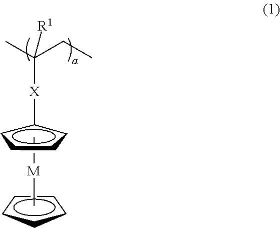
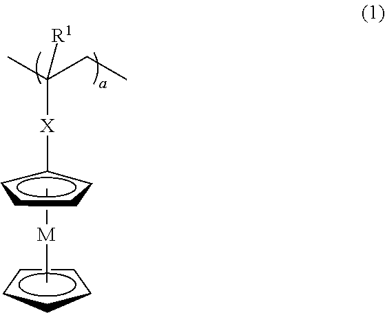
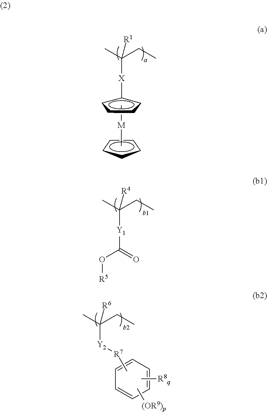
The invention provides a positive resist composition, wherein a polymer compound having the weight-average molecular weight in the range of 1,000 to 500,000 and comprising a repeating unit having a hydrogen atom in a carboxyl group and / or in a phenolic hydroxy group therein been substituted by an acid-labile group and a repeating unit “a” having a cyclopentadienyl complex shown by the following general formula (1) is used as a base resin therein. There can be a positive resist composition having not only small edge roughness (LER and LWR) while having a higher resolution than conventional positive resist compositions, but also a good pattern form after exposure and an extremely high etching resistance, especially a positive resist composition using a polymer compound suitable as a base resin for a chemically amplifying resist composition; and a patterning process.

Description

BACKGROUND OF THE INVENTION[0001]1. Field of the Invention[0002]The present invention relates to a positive resist composition, especially to a positive resist composition using a polymer compound suitable as a base resin for a chemically amplifying positive resist composition, and to a patterning process using the same.[0003]2. Description of the Related Art[0004]As LSI advances toward higher integration and processing speed, miniaturization of the pattern rule is progressing rapidly. Especially expansion of the flash memory market and increase in the memory capacity lead this miniaturization. The 65-nm node device is being mass-produced by an ArF lithography as the cutting-edge technology for miniaturization; and mass-production of the 45-nm node by an ArF immersion lithography as the next generation technology is under preparation. Candidate for the next generation 32-nm node that is being under investigation includes; the immersion lithography by a super high NA lens formed of a...

Claims


Application Information

Patent Timeline
Patent Type & Authority Applications(United States)
IPC IPC(8): G03F7/039G03F7/30
CPCG03F7/30G03F7/0397G03F7/0043G03F7/0045G03F7/0046G03F7/0392G03F7/40Y10S430/114
Inventor HATAKEYAMA, JUN
Owner SHIN ETSU CHEM IND CO LTD
Learn More