Lubrication of a planetary gear device

A planetary gear and transmission device technology, applied in the direction of gear lubrication/cooling, power unit, control device, etc., can solve the problems of introduction and inability to oil, and achieve the effect of improving anti-seizure and reducing power transmission loss.

Inactive Publication Date: 2012-01-25
TOYOTA JIDOSHA KK
View PDF5 Cites 10 Cited by
  • Summary
  • Abstract
  • Description
  • Claims
  • Application Information

AI Technical Summary

Problems solved by technology

Therefore, when the oil flinger 65 is rotated in the reverse direction by the motor 15, the oil is caused to flow to the side away from the inlet of the oil passage 31a, so that oil cannot be introduced into the oil passage 31a.

Method used


Image

  • Lubrication of a planetary gear device
  • Lubrication of a planetary gear device
  • Lubrication of a planetary gear device

Examples


Embodiment Construction

[0034] Hereinafter, embodiments of the present invention will be described in detail with reference to the accompanying drawings.

[0035] Figure 1 to Figure 3 An embodiment of the invention is shown in . First, the general structure of a transaxle for an electric vehicle as one embodiment of the vehicle power transmission device according to the present invention will be described.

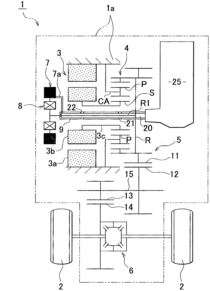
[0036] figure 1 The transaxle 1 and the wheels 2 are shown in . The transaxle 1 mainly includes an electric motor 3 as a power source, a planetary gear device 4 , a reduction gear mechanism 5 , and a differential device (final drive reducer) 6 .

[0037] This transaxle 1 is configured to transmit the rotational power generated by the electric motor 3 to the differential device 6 via the planetary gear unit 4 and the reduction gear mechanism 5, and to transfer the rotational power from the differential as a forward driving force or a reverse driving force. The device 6 is transferred to the w...


PUM


Abstract

A vehicle motive power transmission apparatus includes: a planetary gear device (4); an oil pump (7) for sucking oil present in an apparatus case (1a); a one-way clutch (8) that transmits normal-direction rotation output of the planetary gear device to the oil pump, but does not transmit reverse-direction rotation output of the planetary gear device to the oil pump; an oil tank (25) which is provided in the apparatus case, and which is provided with a first introduction portion that receives oil that is splashed upward as a gear in the apparatus case rotates in a normal direction, and a second introduction portion that receives oil that is splashed upward as the gear rotates in a reverse direction; and an oil passageway (20) that supplies the planetary gear device with oil present in the oil tank or oil sucked by the oil pump.

Description

technical field [0001] The present invention relates to a power transmission device for a vehicle that transmits rotational power generated by a power source to an output side via a planetary gear device. In particular, the present invention relates to a technique of supplying oil to such a planetary gear unit. Background technique [0002] There has been a power transmission device for a vehicle that transmits rotational power generated by, for example, an electric motor to wheels via a planetary gear device (for example, see Japanese Patent Application Publication No. 2007-195320 (JP-A-2007-195320)). [0003] Regarding the prior art according to Japanese Patent Application Publication No. 2007-195320 (JP-A-2007-195320), the abstract of the publication states: "The transmission motor 10G obtained by arranging the electric motor 10 behind the reduction gear mechanism 11 is Used as an in-wheel motor configured under the spring of the vehicle. The output shaft 10b of the moto...

Claims


Application Information

Patent Timeline
Patent Type & Authority Applications(China)
IPC IPC(8): F16H57/04B60K17/356B60K6/52
CPCF16H57/0457B60K17/356F16H57/0486B60K1/00F16H57/0423B60K2001/003F16H57/0476B60K6/26F16H57/045B60K2001/001F16H57/0409F16H57/0434Y02T10/6265Y02T10/62
Inventor 加藤真吾西谷雅文
Owner TOYOTA JIDOSHA KK
Why Eureka
Try Eureka