
Pressurized fluid turbine engine
a turbine engine and pressurized fluid technology, applied in the direction of liquid fuel engines, renewable energy generation, greenhouse gas reduction, etc., can solve the problem that the embodiment does not provide for the respective pair or sets of nozzles to utilize pressurized fluid
Patent Information
- Authority / Receiving Office
- US · United States
- Patent Type
- Patents(United States)
- Current Assignee / Owner
- Publication Date
- 2006-02-14
Smart Images
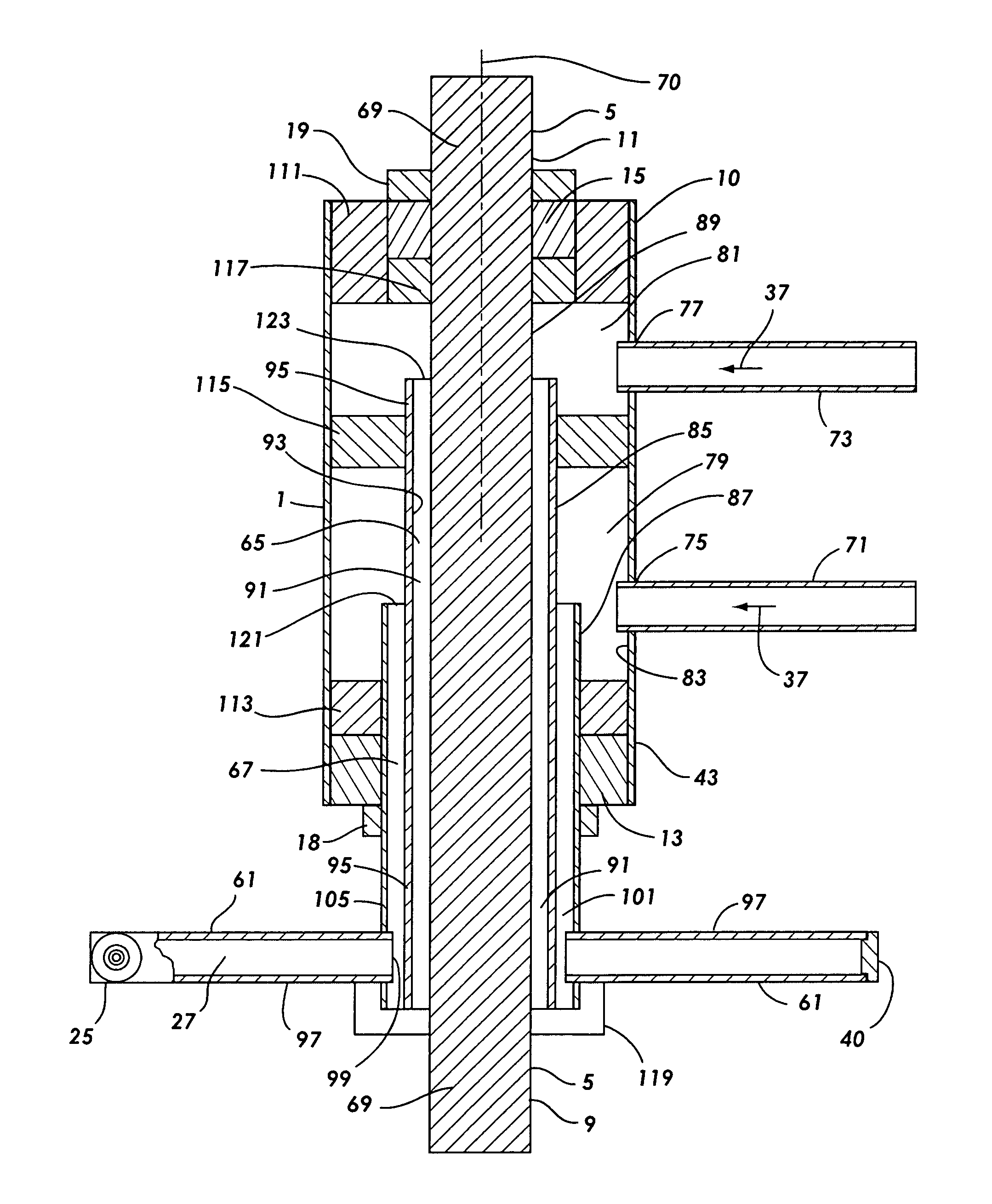
Figure 1 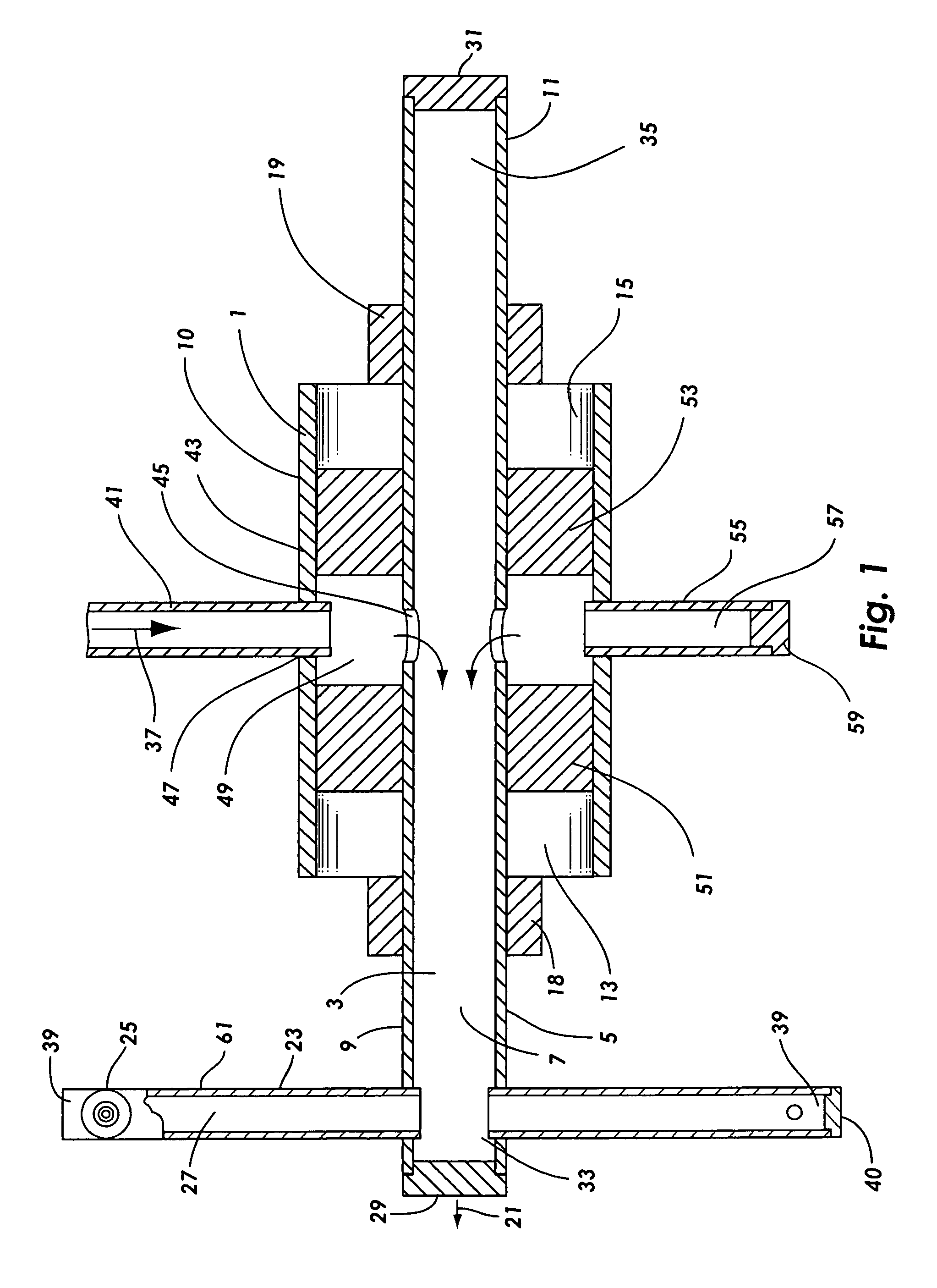
Figure 2 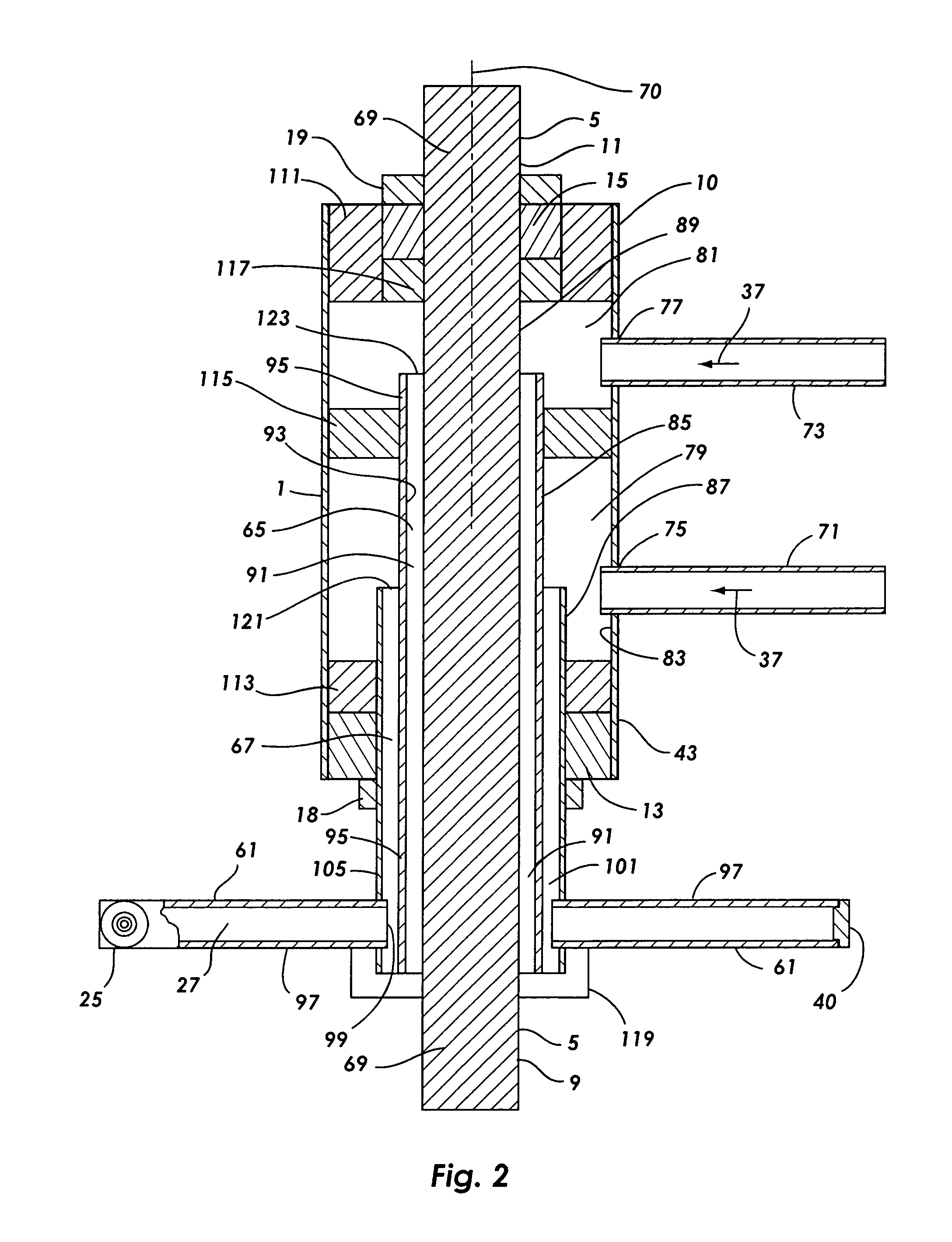
Figure 3
Abstract
Description
FIELD OF THE INVENTION
[0001] This invention is in the field of turbine engines and in particular in the field of pressurized fluid driven bladeless turbine engines.BACKGROUND OF THE INVENTION
[0002] The conventional design for the turbines used in turbine engines incorporates small fins on the turbine. In order for the turbine engine to be efficient, extremely close tolerances are required between the turbine seat of the expansion chamber and the turbine fins. Also, the expansion chamber and the turbine, including the fins, must be able to withstand high temperatures. Because the turbine seat and the fins must be machined to a very close tolerance and must be able to withstand high temperature, they must be constructed of highly durable material. Otherwise, high efficiency will not be achieved and wear will be excessive, rapidly diminishing the efficiency of the engine.
[0003] The pressurized gas turbine engine disclosed in U.S. Pat. No. 6,533,539 to Johnson, the inventor of the present ...
Examples
Embodiment Construction
[0037]Referring first to FIG. 1, a top view horizontal cross-section of a preferred embodiment of the pressurized fluid turbine engine 1 of the present invention with one internal shaft fluid way 3 is shown. This embodiment of the turbine engine has a turbine shaft 5 which has a hollow core 7 which is the shaft fluid way for this preferred embodiment. This embodiment can be provided with a front power take off 9 or a rear power take off 11 or both as shown in FIG. 1. An intake assembly 10 includes a front bearing 13 and a rear bearing 15 to provide for the free rotation of the shaft within an outer housing 43. The bearings are affixed to the outer housing and a front thrust collar 18 and a thrust nut 19 maintain the positioning of the turbine and the bearings and the thrust nut provides for pre-loading the bearings so as to counter the axial thrust 21 imposed on the bearings by normal operation of the turbine engine.
[0038]The bladeless turbine 23 has two or more nozzle arms 61, whic...