Autoclavable endoscope

a technology of endoscope and autoclave, which is applied in the field of autoclavable endoscope, can solve the problems of not providing clear and focused images, known endoscopes tend to lose critical optical characteristics, etc., and achieve the effect of minimizing the change in dimensional characteristics during autoclaving

Active Publication Date: 2006-02-14
BEAVER VISITEC INT US
View PDF4 Cites 20 Cited by
  • Summary
  • Abstract
  • Description
  • Claims
  • Application Information

AI Technical Summary

Benefits of technology

[0015]It is particularly important that the specific epoxy used on the lens which is focused is one that can be cured in a relatively short period of time (15 to 30 minutes) so that the focus established can be permanently set. Since the lens to be focused is proximal of the window and companion lens, that epoxy need not be medical grade.
[0016]A third feature is in the use of a preshrunk thermoplastic elastomer jacket material to enclose the three optical systems throughout the flexible zone proximal of the hand piece. The preshrinking of this material minimizes its dimensional change during autoclaving. The term preshrunk herein refers to preshrinking at high temperature.
[0017]A fourth feature relates to an appropriate construction of the connector at the proximal end of the light fiber. The light fiber portion of the light guide is sealed to a copper ferule with a high temperature epoxy that retains its structure under high temperature to minimize injury of the fragile light fiber system, which injury occurs if the epoxy melts or runs. The material of the ferule is copper so as to dissipate the heat from the xenon light source. This will further serve to minimize injury to the fragile light fiber system. The copper ferule is within an aluminum connector.
[0018]The camera connector, which in the prior art is a plastic material, is replaced by anodized aluminum. This avoids swelling during autoclaving. It is a necessary change to make sure that after autoclaving the connector will couple into the socket of a camera.

Problems solved by technology

Essentially, when autoclaved, the known endoscopes tend to lose their critical optical characteristics and do not provide the clear and focused image that is required for a surgical operation.

Method used


Image

  • Autoclavable endoscope
  • Autoclavable endoscope
  • Autoclavable endoscope

Examples


Embodiment Construction

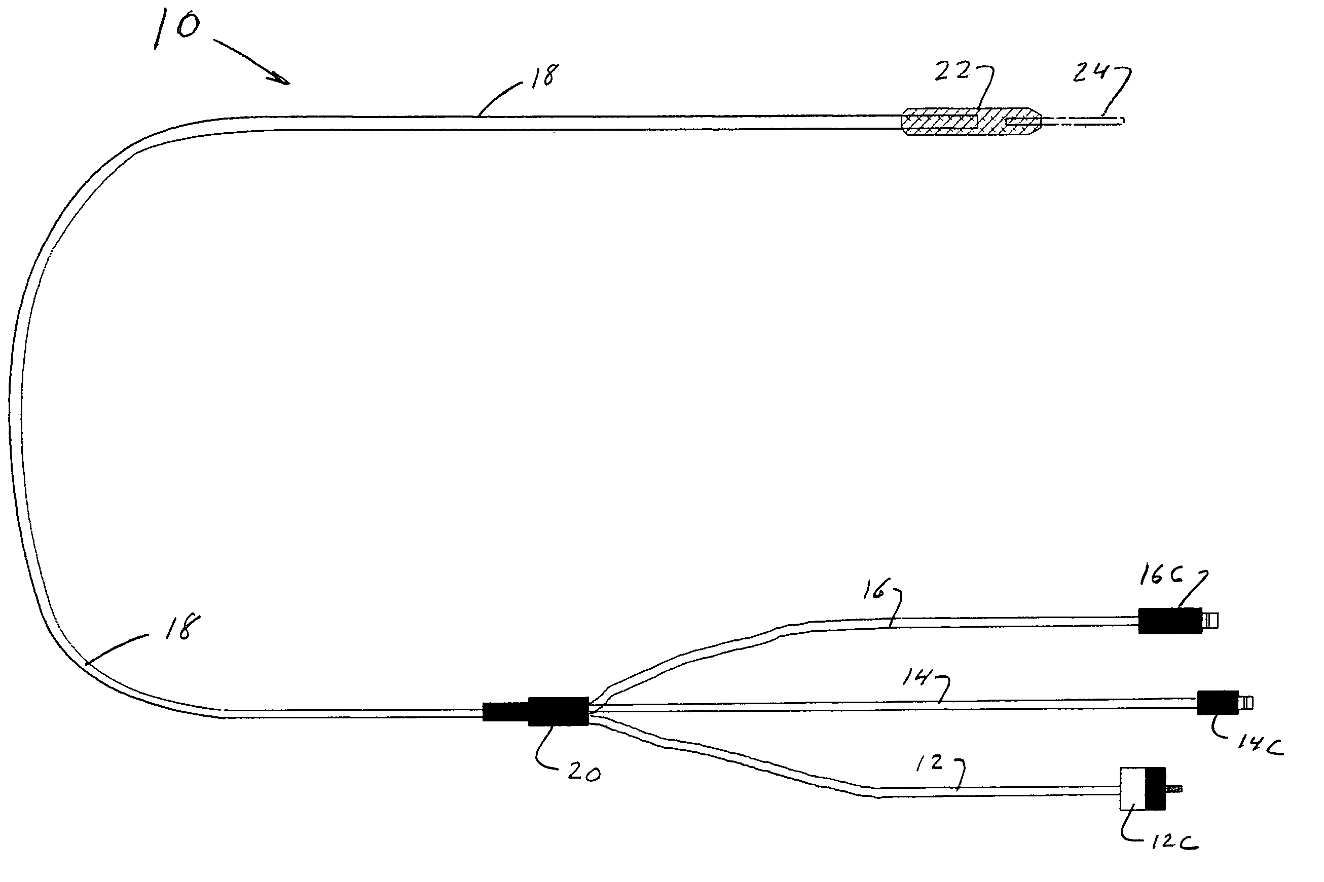
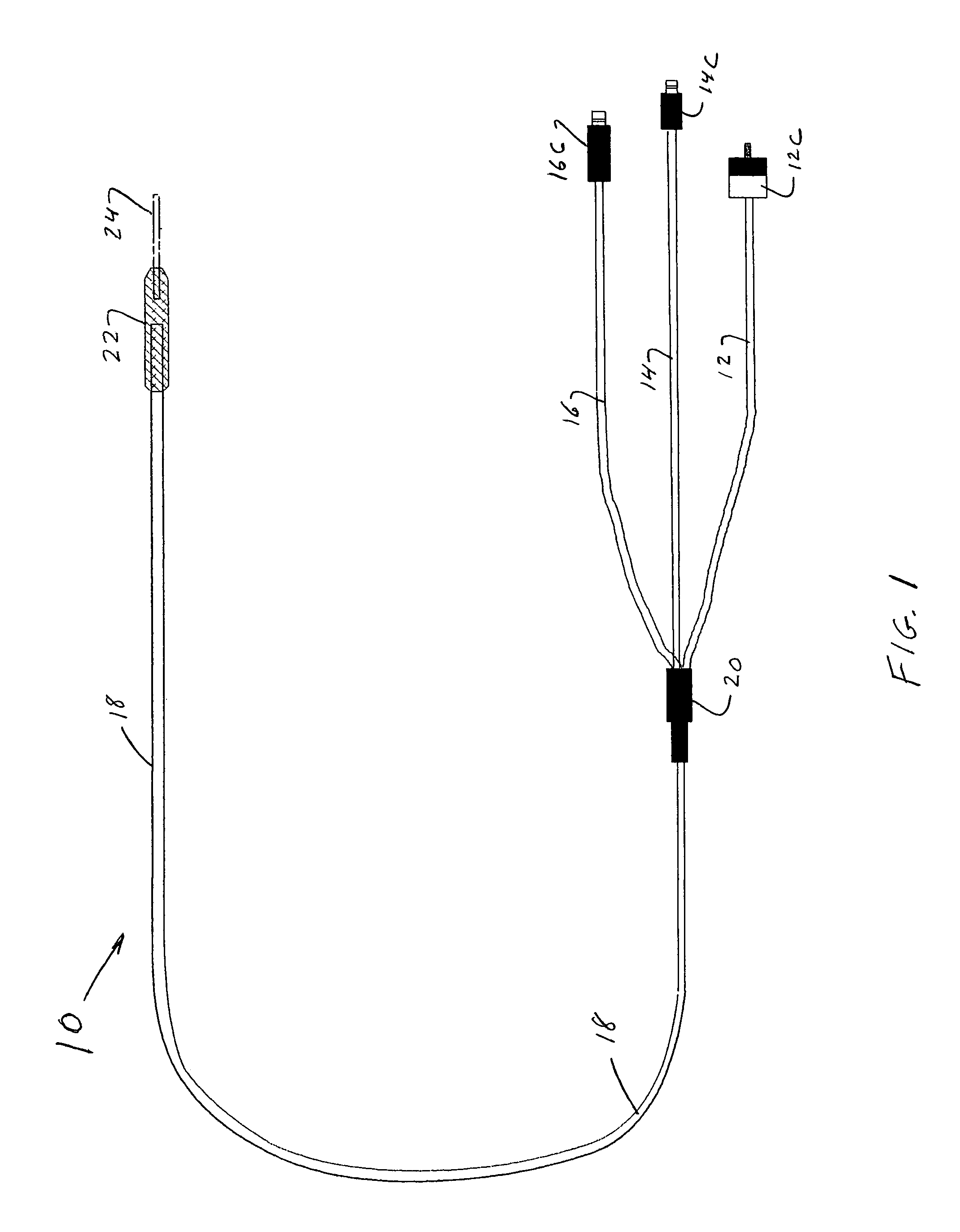
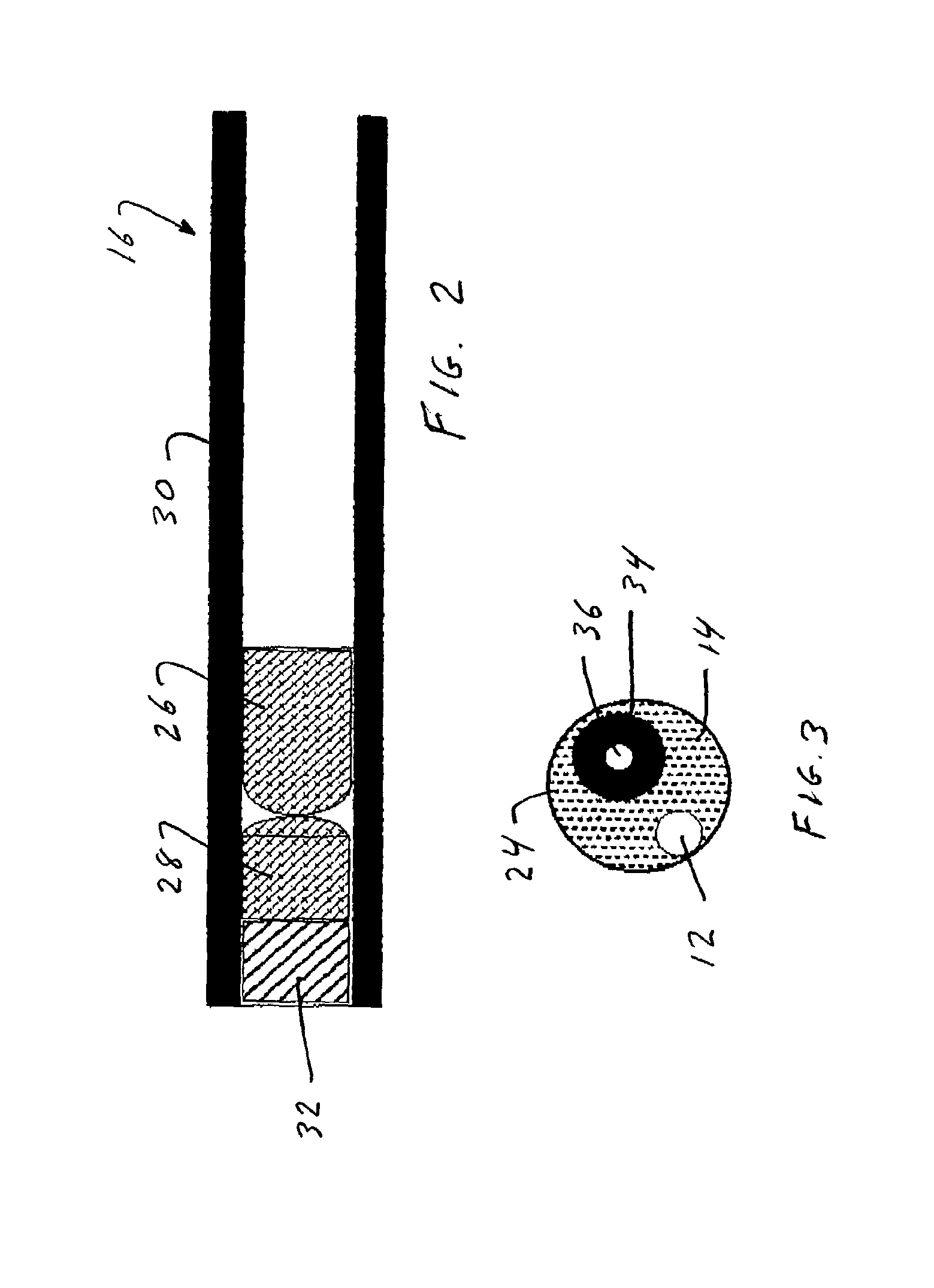
[0023]The FIGs. illustrate a single embodiment. This endoscope 10 has three main optical guides. They are a laser fiber guide 12, a set of fibers to provide a light guide 14 and an image guide 16 having approximately 10,000 light elements to provide 10,000 pixels. These three optical guides 12, 14 and 16 are held in a plastic jacket 18. This jacket 18 extends from a trifurcation zone 20 to the hand piece 22 near the distal end of the endoscope 10.

[0024]Distal of the hand piece 22 is the stainless steel cylindrical probe 24. The three light guides 12, 14, 16 extend through the probe 24 and are flush with the distal end of the probe 24.

[0025]Proximal of the trifurcation zone 20, the three optical guides are in three separate jackets extending to appropriate connectors 12C, 14C, 16C of the optical systems to a laser, a light source and a camera, respectively.

[0026]Specifically, connector 12C at the distal end of the laser fiber guide 12 permits coupling to a laser. A connector 14C at t...


PUM


Abstract

An autoclavable endoscope, such as the type used in ophthalmological operations, has a probe that contains optical fiber guides such as an image guide, a laser guide and an illumination guide. The distal end of these guides are sealed to the distal end of the probe with a high temperature medical grade epoxy. The epoxy is selected to retain its structural and optical properties at autoclaving conditions. A preshrunk flexible plastic jacket extends proximal of the handle around the three guides. Because it is preshrunk at autoclavable temperatures, it is not further damaged during autoclaving. The epoxies used proximal to the probe have to be high temperature epoxies but are generally preferably a more flexible urethane type epoxy. Proximal connectors and ferule for the guides are selected metals to retain size and / or conduct heat.

Description

BACKGROUND OF THE INVENTION[0001]This invention relates in general to a design that makes possible the autoclaving of a fiberoptic endoscope used for medical purposes.[0002]One application of this invention is to an endoscope used in certain ophthalmologic operations. The disclosure herein relates to that embodiment.[0003]As shown, for example, in Applicant's U.S. Pat. No. 5,121,740 issued Jun. 16, 1992, it is known to provide an endoscope which may contain an optical fiber illumination guide, an optical fiber laser guide and an optical fiber image guide to perform surgical operations in various parts of the eye.[0004]It is important that such an endoscope, as well as other types of endoscopes used for other surgical operations, be sterilized between each use or, if that cannot be satisfactorily done, disposed of after first use.[0005]In some venues, it is acceptable to employ a high level disinfectant after the use of the endoscope so that it can be reused. In other venues, only th...

Claims


Application Information

Patent Timeline
Patent Type & Authority Patents(United States)
IPC IPC(8): A61B1/04
CPCA61B1/0011A61B1/0017G02B23/2492A61B1/042A61B2019/4868A61B2090/0813
Inventor URAM, MARTIN
Owner BEAVER VISITEC INT US
Why Eureka
Try Eureka