Rapid exchange catheter with detachable hood

a technology of hood and catheter, which is applied in the field of catheters, can solve the problems of time-consuming and cumbersome guidewire exchange, relatively more time-consuming and costly procedures, and reduce the distal portion of the shaft profile, and facilitate single-operator us

Inactive Publication Date: 2006-02-14
SCI MED LIFE SYST
View PDF106 Cites 111 Cited by
  • Summary
  • Abstract
  • Description
  • Claims
  • Application Information

AI Technical Summary

Benefits of technology

[0012]The present invention provides a single operator exchange biliary catheter having a common distal lumen thereby reducing the profile of the distal portion of the shaft. In an exemplary embodiment, the present invention provides a biliary catheter including an elongate shaft having a proximal portion defining an ancillary lumen and a distal portion defining a common guidewire and ancillary lumen. The elongate shaft includes a proximal guidewire port disposed between the proximal end of the shaft and the distal guidewire port to facilitate single operator use.

Problems solved by technology

The exchange of devices over a 450 cm guidewire is both time consuming and cumbersome.
The additional hands required due to the length of the guidewire results in a relatively more time consuming and costly procedure.

Method used


Image

  • Rapid exchange catheter with detachable hood
  • Rapid exchange catheter with detachable hood
  • Rapid exchange catheter with detachable hood

Examples


first embodiment

[0148]Refer now to FIG. 19A, which illustrates a detailed side view of the junction between the proximal shaft portion 806 and the distal shaft portion 808. FIGS. 20A–22A are cross-sectional views taken along lines 20A—20A, 21A—21A and 22A—22A, respectively, in FIG. 19A. As best seen in 20A, a seal 830 is disposed adjacent the proximal guidewire port 812. The seal 830, in this exemplary embodiment, is a duckbill-type one-way valve. However, the seal 830 may comprise any of the types discussed previously.

[0149]Duckbill-type valve 830 may comprise an elastomeric tube 831 mounted to a rigid tube 832 disposed in the guidewire lumen at the juncture between the proximal shaft portion 806 and the distal shaft portion 808. The elastic tube 831 may have a flattened distal portion or may comprise a tubular structure having opposing flaps formed in the distal end thereof by cutting two opposing slits through the wall of the tubular structure. Rigid tube 832 may comprise a stainless steel hypot...

second embodiment

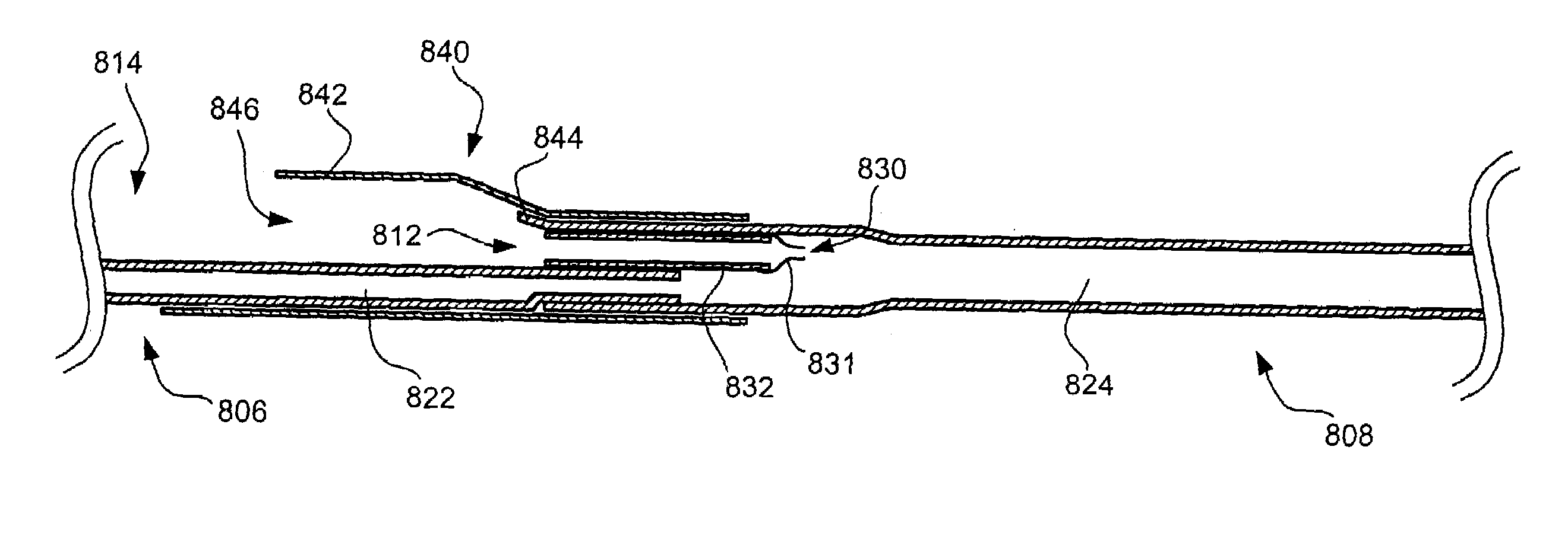
[0151]Refer now to FIG. 19B, which illustrates a detailed side view of the junction between the proximal shaft portion 806 and the distal shaft portion 808. Except as described herein, the embodiment illustrated in 19B is the same in form and function as the embodiment illustrated in FIG. 19A. FIGS. 20B–22B are cross-sectional views taken along lines 20B—20B, 21B—21B and 22B—22B, respectively, in FIG. 19B.

[0152]As best seen in FIG. 20B, a hood 840 is provided adjacent the proximal guidewire port 812 to facilitate easy insertion of the guidewire. Hood 840 includes an enlarged proximal portion 842, preferably having an oval shape, wherein the minor diameter is approximately equal to the diameter of the proximal shaft portion 806 and the major diameter is substantially larger than the proximal shaft portion 806. The proximal portion 842 defines an entrance 846 that has a diameter substantially larger than the diameter of the proximal guidewire port 812, and into which the guidewire may...

third embodiment

[0153]Refer now to 19C, which illustrates a detailed side view of the junction between the proximal shaft portion 806 and the distal shaft portion 808. Except as described herein, the embodiment illustrated in FIG. 19C is the same in form and function as the embodiment illustrated in FIG. 19A. In addition, although not illustrated, the hood 840 discussed with reference to FIG. 19B may be utilized in the embodiment illustrated in FIG. 19C. FIGS. 20C–22C are cross-sectional views taken along lines 20C—20C, 21C—21C and 22C—22C, respectively, in FIG. 19C.

[0154]As best illustrated in FIG. 20C, this embodiment differs from the embodiments described previously in that the distal shaft portion 808 is inserted into a cored-out portion of the proximal shaft portion 806. Specifically, the distal end of the proximal shaft portion 806 is cored or hollowed to define a circular interior with a single wall exterior. The proximal end of the distal shaft portion 808 is inserted into the cored distal ...


PUM


Abstract

A single operator exchange biliary catheter having a common distal lumen. The biliary catheter includes an elongate shaft having a proximal portion defining an ancillary lumen and a distal portion defining a common guidewire and ancillary lumen. The common distal lumen reduces the profile of the distal portion of the shaft. The elongate shaft also includes a proximal guidewire port disposed between the proximal end of the shaft and the distal end of the shaft to facilitate single operator use. A seal may be disposed adjacent the proximal guidewire port to thereby seal the port. Preferably, the shaft includes a single lumen distal portion and a bi-lumen proximal portion. The single lumen distal portion of the shaft may be curved and may include a tapered or spherically shaped distal tip.

Description

CROSS REFERENCE TO RELATED APPLICATIONS[0001]This application is a continuation of application Ser. No. 09 / 519,649, filed Mar. 6, 2000 now U.S. Pat. No. 6,520,951; which is a continuation-in-part of U.S. patent application Ser. No. 09 / 312,340, filed on May 14, 1999, entitled “Single Operator Exchange Biliary Catheter with Common Distal Lumen”, now U.S. Pat. No. 6,364,093; which is a continuation-in-part application of U.S. patent application Ser. No. 09 / 080,520, filed on May 18, 1998, entitled “Guidewire and Catheter Locking Device and Method”, now U.S. Pat. No. 6,096,009; which is a continuation-in-part application of U.S. patent application Ser. No. 08 / 926,200, filed on Sep. 9, 1997, entitled “Single Operator Exchange Biliary Catheter”, now U.S. Pat. No. 6,007,522; which claims priority to U.S. Provisional Application No. 60 / 025,235, filed Sep. 13, 1996, entitled “Single Operator Exchange Biliary Catheter”, the entire disclosures of which are hereby incorporated by reference. This...

Claims


Application Information

Patent Timeline
Patent Type & Authority Patents(United States)
IPC IPC(8): A61M5/178A61B1/00A61M25/00A61M25/01A61M25/02A61M25/09A61M29/02A61M39/00
CPCA61M25/0075A61M25/0097A61M25/0169A61M2025/09125A61M2025/018A61M2025/0183
Inventor CARRILLO, JR., OSCAR R.YEARICK, JAMESALLMAN, ROBERT C.ALVAREZ DE TOLEDO, FERNANDOCIANNELLA, MICHAELEVANS, STEPHEN C.
Owner SCI MED LIFE SYST
Why Eureka
Try Eureka