
Sensor having membrane

Inactive Publication Date: 2006-02-14
DENSO CORP
View PDF8 Cites 0 Cited by
  • Summary
  • Abstract
  • Description
  • Claims
  • Application Information

AI Technical Summary

Benefits of technology

[0007]In view of the above problem, it is an object of the present invention to provide a sensor having a membrane, stress on which is reduced so that the sensor is limited to crack and to be broken.

Problems solved by technology

However, this makes the manufacturing cost increase.

Method used


Image

  • Sensor having membrane
  • Sensor having membrane
  • Sensor having membrane

Examples


Embodiment Construction

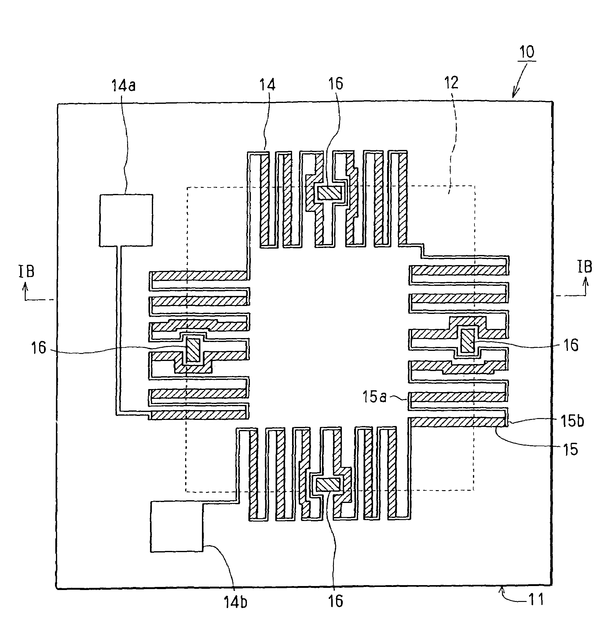
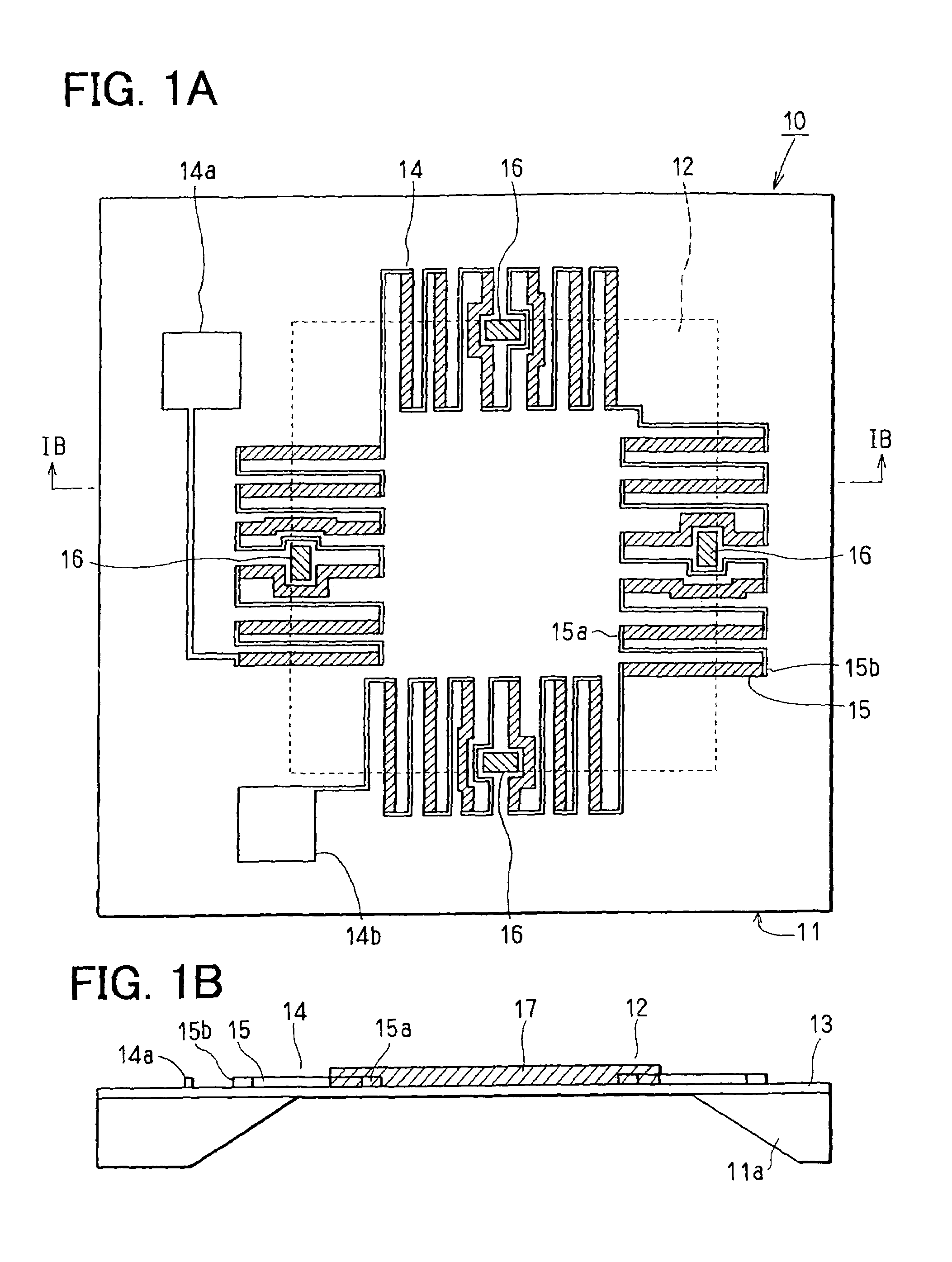
[0024]A sensor 10 according to a preferred embodiment of the present invention is shown in FIGS. 1A and 1B. The sensor 10 is composed of a sensor chip 11 for sensing infrared light. The sensor chip 11 is formed with fabricating a silicon substrate 11a. On an upper surface of the sensor chip 11, a thin film 13 is formed for providing a membrane 12. The membrane 12 is formed in such a manner that a lower surface of the silicon substrate 11a is etched so as to expose the thin film 13. On the lower side of the silicon substrate 11a, the thin film 13 is exposed to have a rectangular shape. Therefore, the membrane 12 has the rectangular shape in a plan view.

[0025]On the thin film 13, a thermopile 14 is formed. The thermopile 14 is provided by a plurality of thermocouples 15 connected with series connection. Each thermocouple 15 has a hot contact point 15a and a cold contact point 15b. The hot contact point 15a is disposed on the membrane 12, and the cold contact point 15b is disposed on t...


PUM


Abstract

A sensor includes a detector for detecting physical quantity, a membrane, and a stress relaxation area. A stress is expected to concentrate in the stress relaxation area in a case of manufacturing process of the sensor or a case of operating the sensor. The detector is disposed on the membrane except for the stress relaxation area.

Description

CROSS REFERENCE TO RELATED APPLICATION[0001]This application is based on Japanese Patent Applications No. 2002-310978 filed on Oct. 25, 2002, and No. 2003-275312 filed on Jul. 16, 2003, the disclosures of which are incorporated herein by reference.FIELD OF THE INVENTION[0002]The present invention relates to a sensor having a membrane.BACKGROUND OF THE INVENTION[0003]A sensor 100 having a membrane structure according to a prior art is shown in FIGS. 8A and 8B. The sensor 100 is a thermopile type infrared sensor, and disclosed in Japanese Unexamined Patent Application Publication No. H04-98883. The sensor 100 has a thin film membrane 112. A hot contact point 115a of a thermocouple 115 (i.e., a hot junction 115a of a thermocouple 115) is disposed on the membrane 112 so that thermal separation between the hot contact point 115a and a cold contact point 115b of the thermocouple 115 (i.e., a cold junction 115b of the thermocouple 115) is improved.[0004]In the above sensor 100, an upper su...

Claims


Application Information

Patent Timeline
IPC IPC(8): G01J5/00G01J1/02G01L1/18G01J5/02G01J5/12G01J5/14H01L35/32
CPCG01J5/12
Inventor HAMAMOTO, KAZUAKITOYODA, INAO
Owner DENSO CORP
Learn More