Transflective liquid crystal display device having particular angles between optical axes

a liquid crystal display and optical axes technology, applied in liquid crystal compositions, instruments, chemistry apparatus and processes, etc., can solve the problems of low visibility of reflective lcds, increased power consumption, and usually consuming 50% or more of the total power consumed by lcd devices

Active Publication Date: 2006-02-14
AU OPTRONICS CORP
View PDF2 Cites 12 Cited by
  • Summary
  • Abstract
  • Description
  • Claims
  • Application Information

AI Technical Summary

Benefits of technology

[0013]According to the foregoing description, an object of this invention is to provide a transflective liquid crystal display (LCD) with a single gap. By accurately controlling relative positions of each optical element in the LCD, color difference between a reflective region and a transmissive region, caused by the transflective LCD with a single gap, can be prevented.

Problems solved by technology

The backlight usually consumes 50% or more of the total power consumed by the LCD device.
Therefore, power consumption is increased due to the use of backlight.
The reflective type LCD has the drawback of low visibility when ambient light decreases.
In contrast, the drawback of the transmissive type LCD is that the visibility is very low when the ambient light is very bright.
Since the display is darker than the ambient light, the quality of color reproduction suffers.
However, enhancing the light intensity of the backlight increases power consumption.
Moreover, when the LCD is exposed to sunlight or another light source, the image quality of the display decreases considerably.
For example, when the sunlight or another light source is directly incident to the LCD monitor, it is difficult to view the displayed image due to reflection.

Method used


Image

  • Transflective liquid crystal display device having particular angles between optical axes
  • Transflective liquid crystal display device having particular angles between optical axes
  • Transflective liquid crystal display device having particular angles between optical axes

Examples


example 1

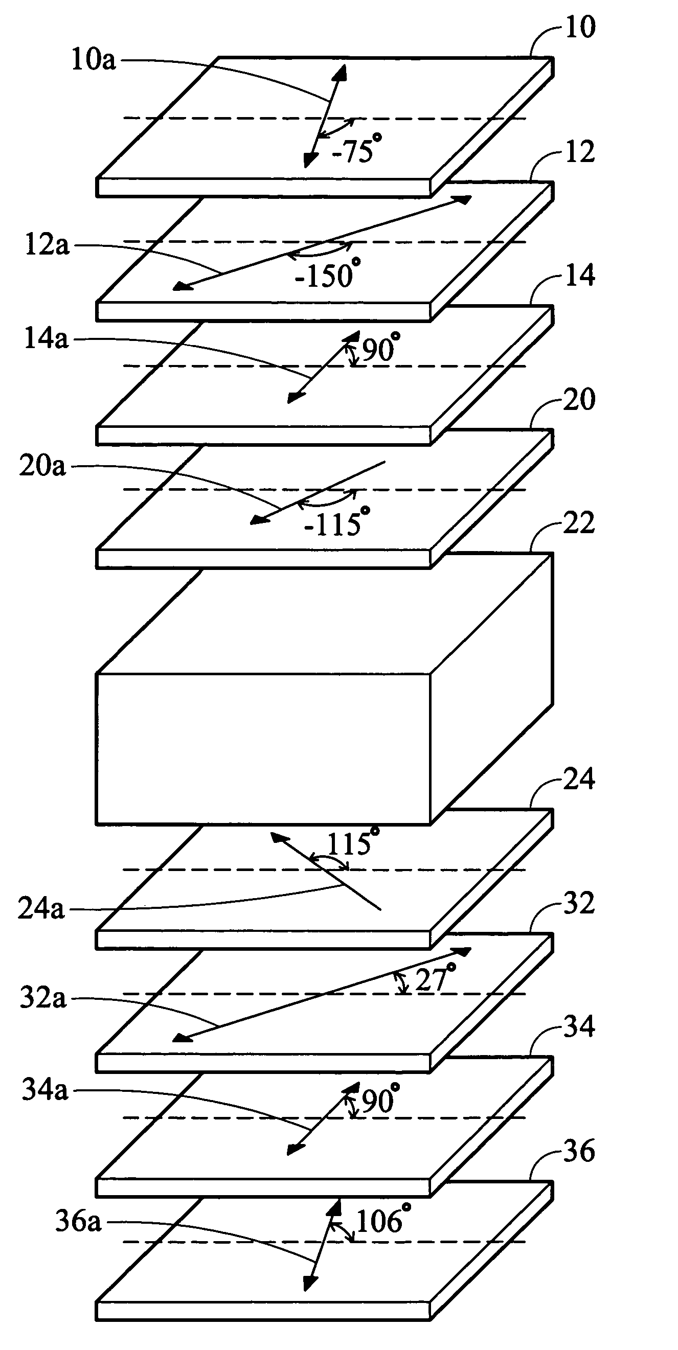
[0048]Example 1 is described in detail according to FIG. 4. In Example 1, the twist angle of the liquid crystal layer 22 is 50°, the thickness d of the liquid crystal layer 22 is 35 μm, Δn of the liquid crystal molecules of the liquid crystal layer 22 is ne−no=0.064, wherein ne is the refraction index of the liquid crystal molecules with respect to the extraordinary light and no is the refraction index of the liquid crystal molecules with respect to the ordinary light. The retardation (Δn×d)LC of the liquid crystal cell is 0.064×0.35 μm=224 nm.

[0049]The rubbing direction 20a of the alignment film 20 above the liquid crystal layer 22 and a horizontal reference line H forms an angle of −115°, and the rubbing direction 20a is from the upside down to the left side. The rubbing direction 24a of the alignment film 24 under the liquid crystal layer 22 and the horizontal reference line H forms an angle of 115°, and the rubbing direction 24a is from the downside up to the left side.

[0050]The...


PUM

PropertyMeasurementUnit
twist angleaaaaaaaaaa
angleaaaaaaaaaa
angleaaaaaaaaaa

Abstract

A transflective liquid crystal device capable of balancing a color difference between a reflective region and a transmissive region. The arrangement conditions of optical elements in the transflective LCD are as follows. The twist angle of the liquid crystal is about 40°˜80°. The angles βup, βdown, θup and θdown are about −20°˜−60°, −20°˜20°, 60°˜110°, −30°˜20° respectively. The angle between the retardation axes of the upper λ/2 plate and the upper λ/4 plate is about 30°˜100°, and the angle between the retardation axes of the lower λ/2 plate and the lower λ/4 plate is about 30°˜80°.

Description

BACKGROUND OF THE INVENTION[0001]1. Field of the Invention[0002]This invention relates in general to a transflective liquid crystal display (LCD). More particularly, this invention relates to a transflective liquid crystal display (LCD) with a single gap type and capable of balancing a color difference between the reflective and transmissive regions.[0003]2. Description of the Related Art[0004]Due to the characteristics of thin profile and low power consumption, liquid crystal displays (LCDs) have been widely used in electronic products, such as portable personal computers, digital cameras, projectors, etc.[0005]Unlike CRTs (cathode ray tubes) and EL (electroluminescent) devices, LCDs do not emit light themselves, hence, transmissive LCDs require a backlight module. The backlight usually consumes 50% or more of the total power consumed by the LCD device. Therefore, power consumption is increased due to the use of backlight.[0006]For solving the aforementioned problem, a reflective t...

Claims


Application Information

Patent Timeline
Patent Type & Authority Patents(United States)
IPC IPC(8): G02F1/1335G02F1/13363
CPCG02F1/133555G02F1/13363G02F2413/08G02F2001/1398G02F2413/04G02F2001/133638G02F1/133638G02F1/1398
Inventor WU, YANG-ENCHEN, PO-LUN
Owner AU OPTRONICS CORP
Why Eureka
Try Eureka