
Body support surface comfort device

a comfort device and body support technology, applied in the direction of foam mattresses, beds, chairs, etc., can solve the problems of foam deformation, affecting the comfort of people, so as to achieve the effect of convenient adjustmen

Inactive Publication Date: 2006-02-21
CHAFFEE ROBERT B
View PDF128 Cites 24 Cited by
  • Summary
  • Abstract
  • Description
  • Claims
  • Application Information

AI Technical Summary

Benefits of technology

[0009]In view of the problems and disadvantageous of the above described structures, there is a need to find an alternative to the thin foam surface comfort devices as well as the inflatable devices described above. In particular, there is a need for a device that can conform to a shaped surface, a beveled surface, a contoured surface, a cushioned surface and the like, and that can equally distribute pressure applied to the device, for example, when one sits on a devi...

Problems solved by technology

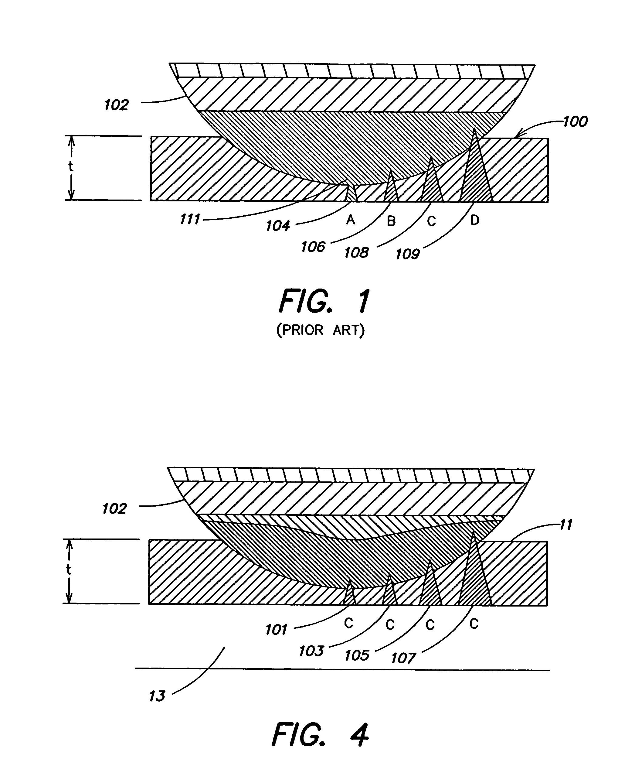
One problem with these foam layer devices is that the foam layer must be thin to accommodate shaped devices, and foam is a compressible material which compacts at a point where pressure is applied.
Thus, the thin layer of foam typically does not equally distribute the applied pressure or weight and typically provides at least one pressure point and discomfort point to the user of the thin foam device.
Another problem with foam devices is that the performance of foam degrades over time and can vary with environmental conditions.
In addition, the thin foam device 100 does not supportively conform to a surface or subject applying pressure to the thin foam device.
Further, the thin foam device may not typically conform to the body support device that it is used with.
However, one problem with some inflatable devices is that they may not be self-sealing, thus requiring a user to fumble with a valve when inflating the device.
These valves are clumsy, are not self-sealing and thus are difficult to adjust an amount of fluid in the device.
Another problem with some inflatable devices is that the inflatable devices are not intended to be used with shaped or cushioned surfaces, and instead are intended to be used on a flat surface.
However, an inflatable mattress would not work well with and would not conform with a shaped surface.
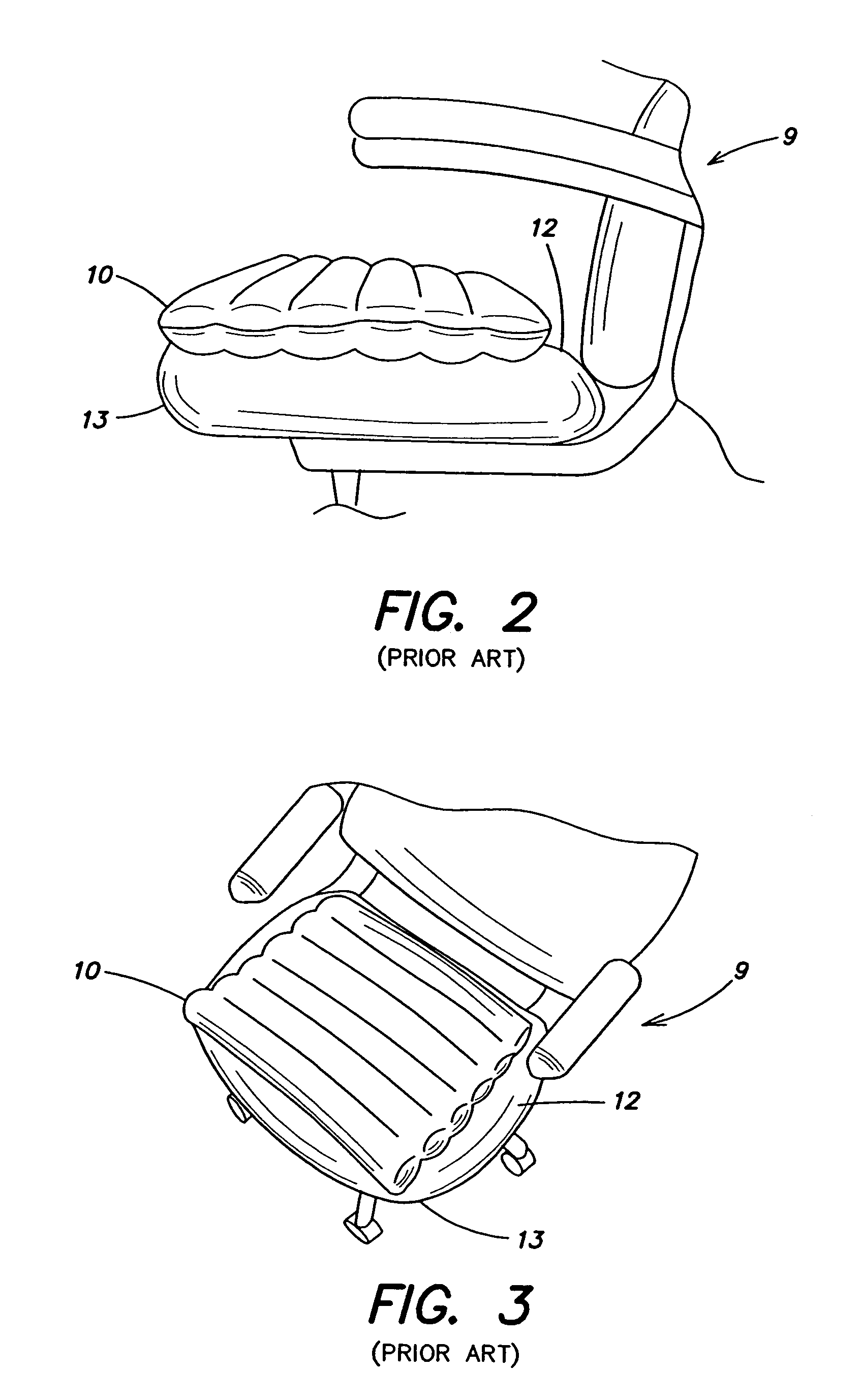
However, the problem with device 10 is that it is not shaped to be used with a shaped surface.
In addition, the device 10 is typically not sized to be compatible with the body support structure.
However, the thickness of the device and the size of the device make it impractical to be used with a shaped surface such as the surface 12 of the seat 13.
In addition, when the device is not fully inflated, it tends to move around the surface 12 and provide an unbalanced cushioning.
Thus, the device 10 is ergonomically incompatible with a shaped surface such as the surface 12 and, does not overspread the entire surface 12, and can be unstable to use with a shaped surface.
Further, the device 10 may not have a mechanism for adjusting an amount of fluid within the device 10, to adjust an amount of support or comfort that the device 10 provides.
For example, the device may have a stem valve as discussed above which requires fumbling with the valve and the mating cover in order to inflate or adjust the amount of fluid in device 10, and therefore there is no easy adjustment mechanism to adjust the amount of fluid in the device 10.

Method used


Image

  • Body support surface comfort device
  • Body support surface comfort device
  • Body support surface comfort device

Examples


embodiment 88

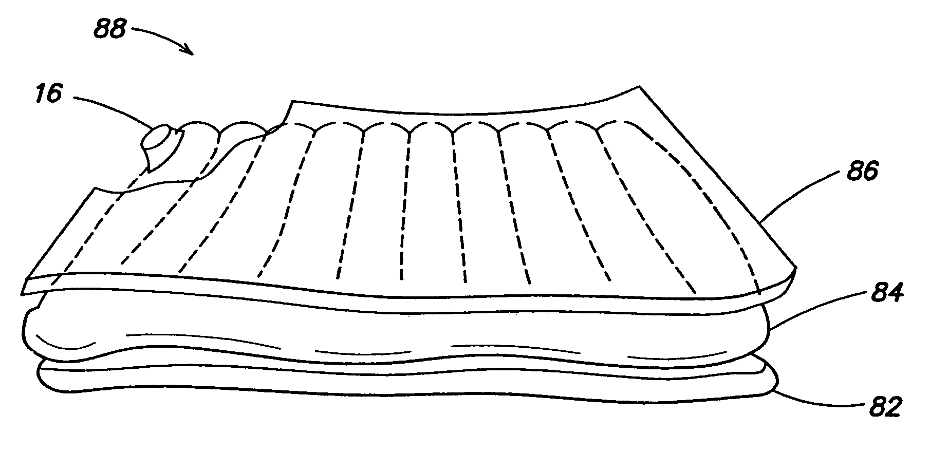
[0033]For example, referring to FIG. 7 there is illustrated another embodiment 88 of a surface comfort device according to the invention. According to this embodiment the surface comfort device comprises a first layer 82, which may be for example a compressible foam or cushioning fabric. The surface comfort device also comprises a second layer 84, which in one embodiment may be an inflatable bladder 11 of the surface comfort device as described herein. The surface comfort device also comprises a third layer 86, which may be, for example, a quilted fabric or a synthetic material, which may include a foam or a textured or contoured cushioning material, or may be fabric sewn with a batting, or a quilted material. An exterior covering layer (not illustrated) of, for example, leather, plastic, or a woven material may also be provided to surround and protect these other layers. It is to be appreciated that this embodiment 88 of the surface comfort device may also include an adjustment dev...

embodiment 20

[0035]Referring again to the embodiment 20 of the surface comfort device illustrated in FIGS. 5–6, it is to be appreciated that the surface comfort device 20 may include an inflatable bladder comprising a plurality of parallel tubes 15. For example, the inflatable surface comfort device may be fabricated with tubes formed by sealing one layer of an air-impervious film directly to another opposing layer of air-impervious film with a number of parallel seams 14, thereby forming a plurality of parallel tubes 15. One advantage of this structure is that it can be easily constructed and is inexpensive. According to this embodiment, the surface comfort device 20 may comprise one or more inflatable bladders formed from at least two layers of air-impervious film, sealed at a perimeter 17 and sealed internally at regular intervals by internal seams 14. Upon inflation, the bladder will comprise a plurality of plural tubes 15 having a generally circular cross-section. It is to be appreciated th...


PUM


Abstract

An adjustable, inflatable surface comfort device to be used with shaped body support devices. The surface comfort device comprises an inflatable bladder having a shape and size to substantially cover at least one support surface of a shaped body support device so as to conform to and provide a comfort layer to the body support device. According to one embodiment, a self-sealing valve is coupled to a port of the inflatable bladder, and is constructed and arranged to enable all of inflation, deflation, and comfort control of the surface comfort device.

Description

RELATED APPLICATIONS[0001]This application is a non-provisional of and claims priority under 35 U.S.C. § 119(e), to provisional application Ser. No. 60 / 371,960, filed Apr. 11, 2002, and provisional application Ser. No. 60 / 374,878, filed Apr. 23, 2002. The contents of these prior application specifications are incorporated herein by reference.FIELD OF THE INVENTION[0002]The present invention relates to an inflatable surface comfort device which may be used with body support devices or as a stand alone comfort device.DISCUSSION OF THE RELATED ART[0003]It is to be understood that a body support structure or body support device, as used herein, includes, for example, a chair seat, a chair back, a head rest, a leg or foot support device, or any other structure or device that is used for, for example, sitting, reclining, lying down, or supporting a person. A body support structure or device typically may be beveled, contoured, angled, or some how shaped for, for example, sitting, reclinin...

Claims


Application Information

Patent Timeline
IPC IPC(8): A47C16/00A47C20/00A47C20/02A47C27/08A47G9/10
CPCA47C4/54A47C7/425A47G9/1027A47C20/023A47C27/081A47C20/021
Inventor CHAFFEE, ROBERT B.
Owner CHAFFEE ROBERT B
Learn More