Top loading fixed line trimmer head

Inactive Publication Date: 2006-02-21
DESERT EXTRUSION CORP
View PDF13 Cites 50 Cited by
  • Summary
  • Abstract
  • Description
  • Claims
  • Application Information

AI Technical Summary

Benefits of technology

[0013]It is an additional object of this invention to provide an improved fixed line trimmer head for string trimmer machines in which the line is simple to install and replace.
[0014]It is yet another object of this invention to provide an improved fixed line trimmer head for string trimmer machines capable of use with lines of different diameters.
[0015]I

Problems solved by technology

A problem exists, however, with bump-and-feed trimmers in that frequently the line which is wound tends to become stuck, either due to partial fusion of the line within the hub, caused by high frequency vibration, or by successive turns of the line wound on the hub becoming somewhat entangled.
As a result, feeding of the line from the hub, when desired, does not always take place.
This is a time consuming and frustrating experience for many users of flexible line string trimmers.
This is awkward and the machine is heavy to hold.
In addition, because of the inverted position of the machine, the possibility of gasoline spillage is ever present.
Bottom loading machines also preclude the utilization of replaceab

Method used


Image

  • Top loading fixed line trimmer head
  • Top loading fixed line trimmer head
  • Top loading fixed line trimmer head

Examples


Embodiment Construction

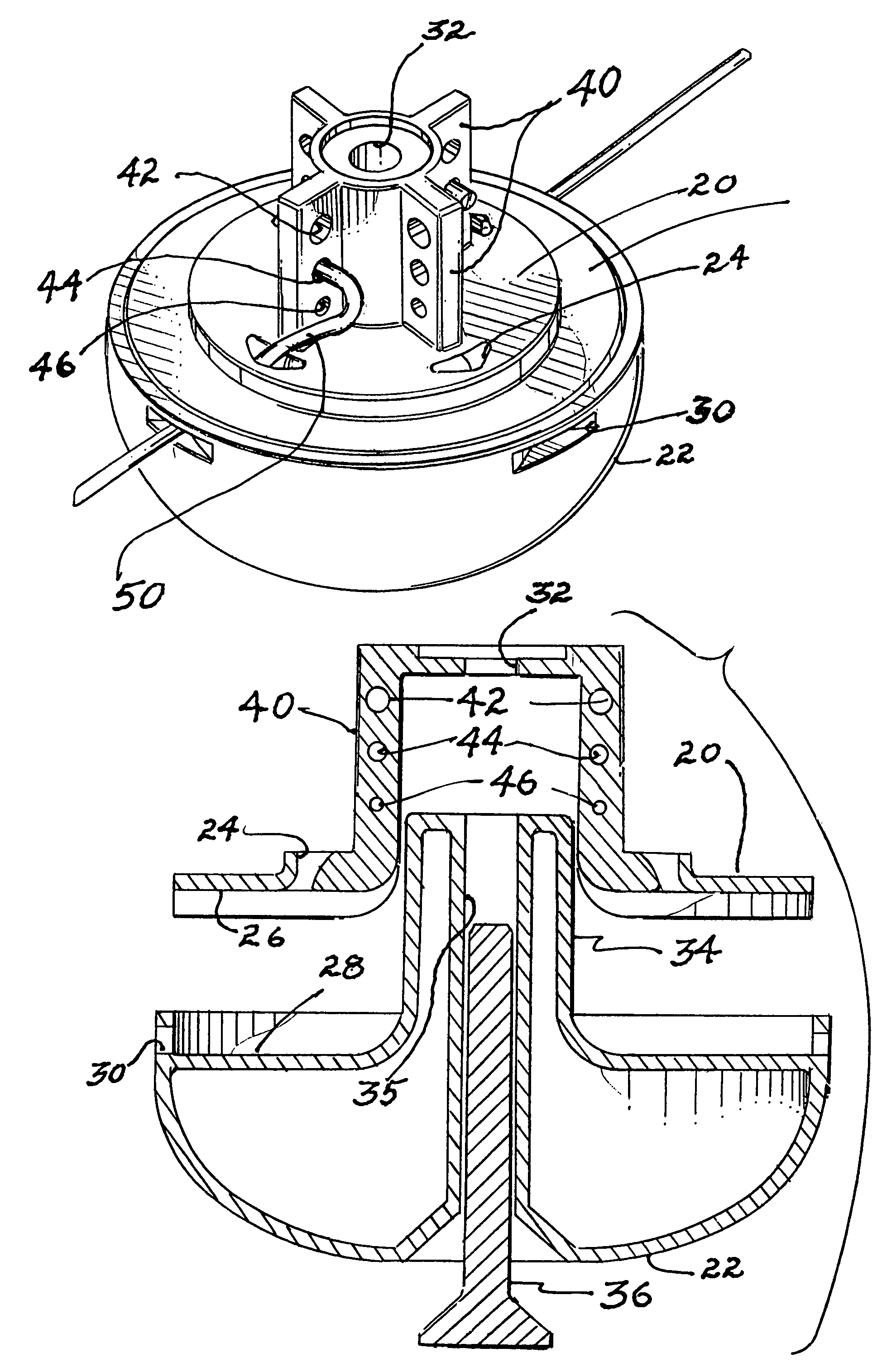
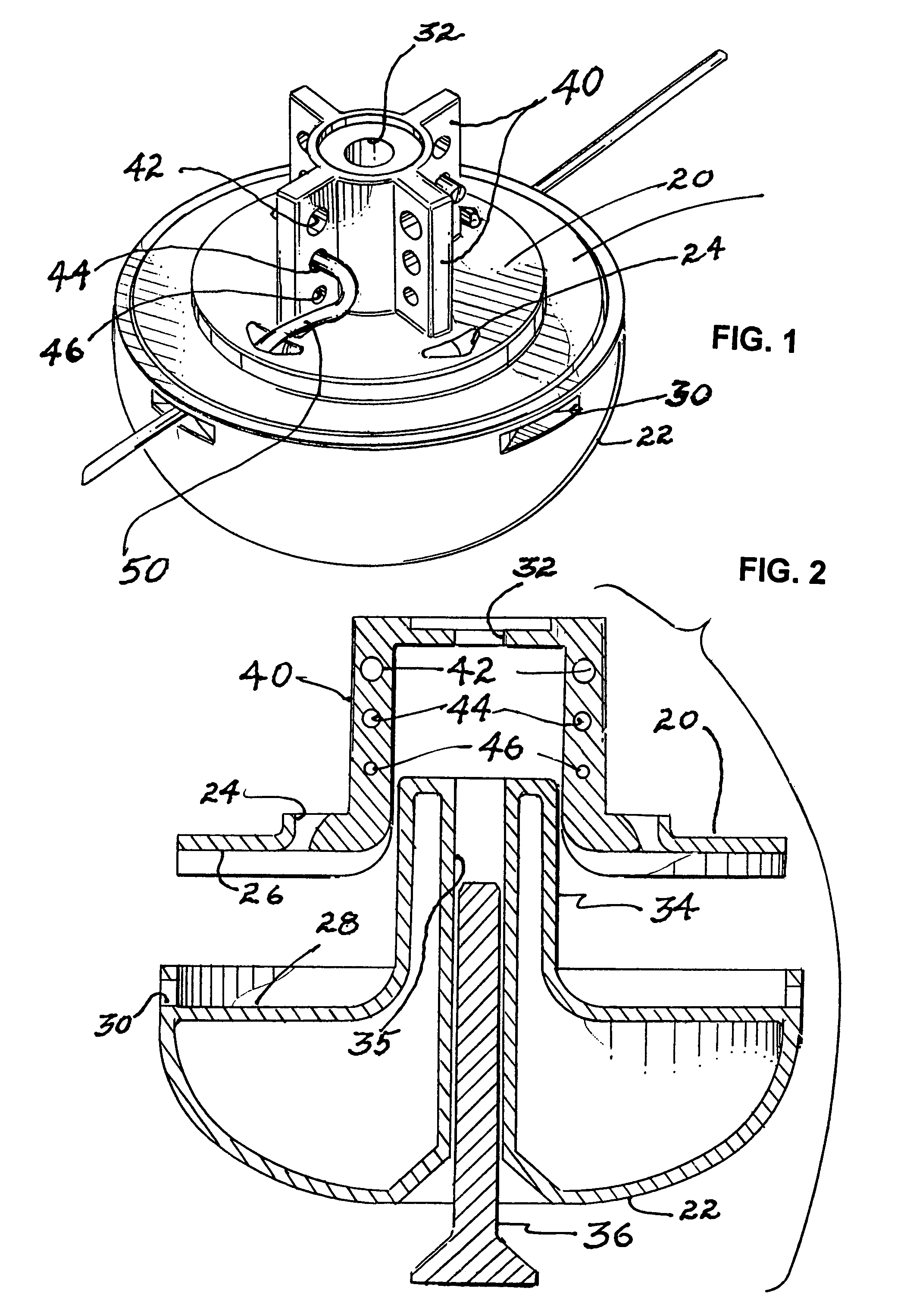
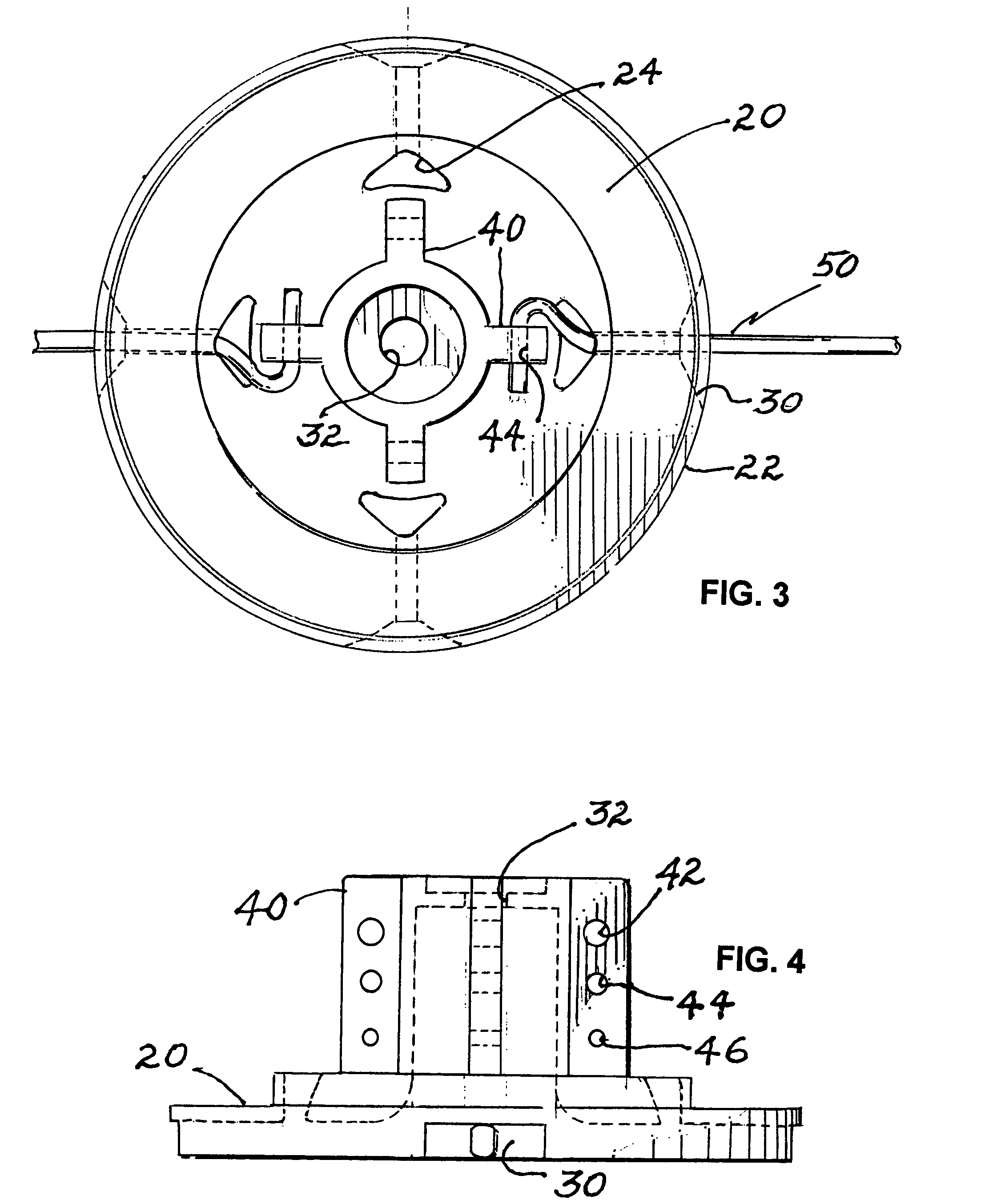
[0032]Reference now should be made to the drawings, in which the same reference numbers are used throughout the different figures to designate the same or similar components. FIGS. 1 through 4 are directed to a preferred embodiment of the invention as applied to a top-loading, fixed length line trimmer head for a string trimmer machine. The trimmer head which is illustrated in FIGS. 1 through 4 may be used in conjunction with either a hand-held trimmer or a high-wheeled brush trimmer. The principles of operation of the head are identical in either application.

[0033]In the embodiment shown in FIGS. 1 through 4, the trimmer head itself comprises an upward extending central cylindrical hub terminating at its lower end in a circular flange 20. The hub itself has a central aperture 32 located in it for receiving a bolt 36 (FIG. 2), which is threaded upwardly through the opening 32 to attach the trimmer head to the drive shaft mechanism of a hand held trimmer or a high wheeled trimmer. Co...


PUM


Abstract

A fixed line top-loading trimmer head for string trimmer machines, uses line segments of a predetermined length. The head has a central hub designed for attachment to the drive shaft of a string trimmer machine. A circular flange is attached to, and extends outwardly from, the central hub. This circular flange has one or more trimmer line exit openings on the circumference. The hub, located above the upper surface of the circular flange, is provided with either line termination apertures in the form of holes or channels which are angularly offset from the exit openings in the circular flange; or it is provided with an offset guide channel through which a trimmer line is passed between the exit openings. A line guide channel is located in the flange between the line exit openings and the line termination apertures, or the offset channel on the hub, for guiding line between the exit openings and the offset channel or termination apertures.

Description

[0001]This application is a continuation of application Ser. No. 09 / 738,678 filed Dec. 15, 2000 now abandoned.BACKGROUND[0002]Weed and grass trimmers have been developed which employ a rotatable hub, with a short length of flexible nylon or other plastic line extending from the hub. When the hub is rotated (typically, at speeds from 6,000 RPM to 12,000 RPM), the tip of the line extending from the hub provides the cutting or trimming action. Weed and grass trimmers using this principle of operation have become popular for their versatility of use, and because the flexible trim line is safer to use than rigid rotating steel blades.[0003]Various types of devices have been developed for using such trimmer lines. Typically, rotating line trimmers or rotating string trimmers employ a line which generally has a circular cross section. In many hand-held trimmers, the line is wound on a storage reel in the hub of the device, and is fed out of a hole in the hub in discrete amounts, as the end...

Claims


Application Information

Patent Timeline
IPC IPC(8): A01D34/84A01D34/416
CPCA01D34/416
Inventor FOGLE, JOHN R.
Owner DESERT EXTRUSION CORP
Why Eureka
Try Eureka